UCD9090
www.ti.com
SLVSA30A –APRIL 2011–REVISED AUGUST 2011
MON(1:10)
3.3V
UCD9090
POWER
SUPPLY
10kW
out
V
GPIO(1:10)
/EN
VOUT
VFB
3.3V
Rmrg_HI
VFB
“0” or “1”
“0” or “1”
GPIO
GPIO
VOUT
Rmrg_LO
3.3V
POWER
SUPPLY
Vout
W
10k
/EN
VOUT
VFB
VFB
Rmrg_HI
VOUT
.
3.3V
Rmrg_LO
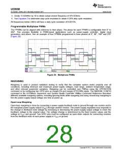
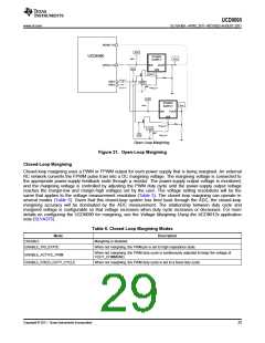
Open Loop Margining
Figure 21. Open-Loop Margining
Closed-Loop Margining
Closed-loop margining uses a PWM or FPWM output for each power supply that is being margined. An external
RC network converts the FPWM pulse train into a DC margining voltage. The margining voltage is connected to
the appropriate power-supply feedback node through a resistor. The power-supply output voltage is monitored,
and the margining voltage is controlled by adjusting the PWM duty cycle until the power-supply output voltage
reaches the margin-low and margin-high voltages set by the user. The voltage setting resolutions will be the
same that applies to the voltage measurement resolution (Table 3). The closed loop margining can operate in
several modes (Table 6). Given that this closed-loop system has feed back through the ADC, the closed-loop
margining accuracy will be dominated by the ADC measurement. The relationship between duty cycle and
margined voltage is configurable so that voltage increases when duty cycle increases or decreases. For more
details on configuring the UCD9090 for margining, see the Voltage Margining Using the UCD9012x application
note (SLVA375).
Table 6. Closed Loop Margining Modes
Mode
Description
DISABLE
Margining is disabled.
ENABLE_TRI_STATE
When not margining, the PWM pin is set to high impedance state.
When not margining, the PWM duty-cycle is continuously adjusted to keep the voltage at
VOUT_COMMAND.
ENABLE_ACTIVE_TRIM
ENABLE_FIXED_DUTY_CYCLE
When not margining, the PWM duty-cycle is set to a fixed duty-cycle.
Copyright © 2011, Texas Instruments Incorporated
29

 TI [ TEXAS INSTRUMENTS ]