UCD9090
SLVSA30A –APRIL 2011–REVISED AUGUST 2011
www.ti.com
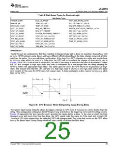
3ms
3ms
3ms
3ms
GPI
GPO
1ms
Figure 19. GPO Behavior When Ignoring Inputs During Delay
State Machine Mode Enable
When this bit within the GPO_CONFIG command is set, only one of the AND path will be used at a given time.
When the GPO logic result is currently TRUE, AND path 0 will be used until the result becomes FALSE. When
the GPO logic result is currently FALSE, AND path 1 will be used until the result becomes TRUE. This provides a
very simple state machine and allows for more complex logical combinations.
GPI Special Functions
There are five special input functions for which GPIs can be used. There can be no more than one pin assigned
to each of these functions.
•
•
•
•
Sequencing Timeout Source - If SEQ_TIMEOUT is non-zero on any rail, a fault will occur if this GPI pin
does not go active within SEQ_TIMEOUT time after the rail reaches its power good state.
Latched Statuses Clear Source - When a GPO uses a latched status type (_LATCH), you can configure a
GPI that will clear the latched status.
Input Source for Margin Enable - When this pin is asserted, all rails with margining enabled will be put in a
margined state (low or high).
Input Source for Margin Low/Not-High - When this pin is asserted all margined rails will be set to Margin
Low as long as the Margin Enable is asserted. When this pin is de-asserted the rails will be set to Margin
High.
The polarity of GPI pins can be configured to be either Active Low or Active High. The first 3 GPIs that are
defined regardless of their main purpose will be used for the PIN_SELECTED_RAIL_STATES command.
Power-Supply Enables
Each GPIO can be configured as a rail-enable pin with either active-low or active-high polarity. Output mode
options include open-drain or push-pull outputs that can be actively driven to 3.3 V or ground. During reset, the
GPIO pins are high-impedance except for FPWM/GPIO pins 17–24, which are driven low. External pulldown or
pullup resistors can be tied to the enable pins to hold the power supplies off during reset. The UCD9090 can
support a maximum of 12 enable pins.
NOTE
GPIO pins that have FPWM capability (pins 10-17) should only be used as power-supply
enable signals if the signal is active high.
Cascading Multiple Devices
A GPIO pin can be used to coordinate multiple controllers by using it as a power good-output from one device
and connecting it to the PMBUS_CNTRL input pin of another. This imposes a master/slave relationship among
multiple devices. During startup, the slave controllers initiate their start sequences after the master has
completed its start sequence and all rails have reached regulation voltages. During shutdown, as soon as the
master starts to sequence-off, it sends the shut-down signal to its slaves.
26
Copyright © 2011, Texas Instruments Incorporated

 TI [ TEXAS INSTRUMENTS ]