UCC28951
www.ti.com.cn
ZHCSIQ7A –AUGUST 2018 –REVISED DECEMBER 2021
It is necessary to prevent the reverse current flow through the synchronous rectifier MOSFETs and output
inductor at light load, during parallel operation and at some transient conditions. Such reverse current results in
circulating of some extra energy between the input voltage source and the load and, therefore, causes increased
losses and reduced efficiency. Another negative effect of such reverse current is the loss of ZVS condition. The
suggested control algorithm prevents reverse current flow, still maintaining most of the benefits of synchronous
rectification by switching off the drive signals of rectifier MOSFETs in a predetermined way. At some pre-
determined load current threshold, the controller disables outputs OUTE and OUTF by bringing them down to
zero.
Synchronous rectification using MOSFETs requires some electrical energy to drive the MOSFETs. There is a
condition below some light-load threshold when the MOSFET drive related losses exceed the saving provided by
the synchronous rectification. At such light load, it is best to disable the drive circuit and use the internal body
diodes of rectifier MOSFETs, or external diodes in parallel with the MOSFETs, for more efficient rectification. In
most practical cases, the drive circuit needs to be disabled close to DCM mode. This mode of operation is called
discontinuous-current diode-rectification mode.
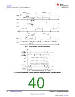
At very light-load and no-load conditions, the duty cycle, demanded by the closed-feedback-loop control circuit
for output voltage regulation, can be very low. This level leads to the loss of ZVS condition and increased
switching losses. To avoid the loss of ZVS, the control circuit limits the minimum ON-time pulse applied to the
power transformer using resistor from TMIN pin to GND. Therefore, the only way to maintain regulation at very
light load and at no-load condition is to skip some pulses. The controller skips pulses in a controllable manner to
avoid saturation of the power transformer. Such operation is called burst mode. In Burst Mode there are always
an even number of pulses applied to the power transformer before the skipping off time. Thus, the flux in the
core of the power transformer always starts from the same point during the start of every burst of pulses.
Copyright © 2023 Texas Instruments Incorporated
Submit Document Feedback
41
Product Folder Links: UCC28951
English Data Sheet: SLUSDB2

 TI [ TEXAS INSTRUMENTS ]