UCC28951
www.ti.com.cn
ZHCSIQ7A –AUGUST 2018 –REVISED DECEMBER 2021
POUT ´0.2
DILOUT
=
= 10A
VOUT
(27)
Take care in selecting the correct amount of magnetizing inductance (LMAG). 方程式 28 calculates the minimum
magnetizing inductance of the primary of the transformer (T1) to ensure the converter operates in current-mode
control. As LMAG reduces, the increasing magnetizing current becomes an increasing proportion of the signal at
the CS pin. If the magnetizing current increases enough, it can swamp out the current sense signal across RCS
and the converter will operate increasingly as if it were in voltage mode control rather than current mode.
V ´(1-DTYP
)
IN
LMAG
³
» 2.78mH
DILOUT ´0.5
´ 2´F
SW
a1
(28)
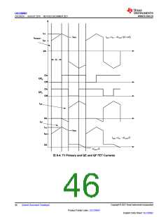
图 8-4 shows T1 primary current (IPRIMARY) and synchronous rectifiers QE (IQE) and QF (IQF) currents with
respect to the synchronous rectifier gate drive currents. IQE and IQF are the same as the secondary winding
currents of T1. Variable D is the duty cycle of the converter.
Copyright © 2023 Texas Instruments Incorporated
Submit Document Feedback
45
Product Folder Links: UCC28951
English Data Sheet: SLUSDB2

 TI [ TEXAS INSTRUMENTS ]