UCC28951
www.ti.com.cn
ZHCSIQ7A –AUGUST 2018 –REVISED DECEMBER 2021
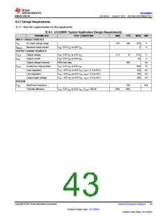
8.2.2 Detailed Design Procedure
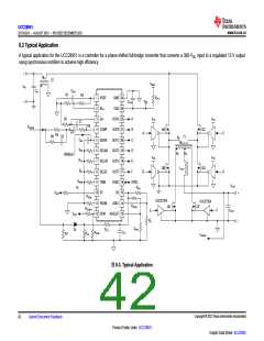
In high-power server applications to meet high-efficiency and green standards some power-supply designers
have found it easier to use a phase-shifted, full-bridge converter. This is because the phase-shifted, full-bridge
converter can obtain zero-voltage switching on the primary side of the converter, reducing switching losses, and
EMI and increasing overall efficiency.
This is a review of the design of a 600-W, phase-shifted, full-bridge converter for one of these power systems
using the UCC28951 device, which is based on typical values. In a production design, the values may need to
be modified for worst-case conditions. TI has provided a MathCAD Design Tool and an Excel Design Tool to
support the system designer. Both tools can be accessed in the Tools and Software tab of the UCC28951
product folder on TI.com, or can be downloaded through the following links: MathCAD Design Tool, Excel Design
Tool.
备注
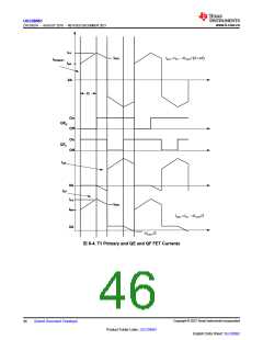
The term fSW refers to the switching frequency applied to the power transformer. The output inductor
experiences a switching frequency that is 2 × fSW
.
8.2.2.1 Power Loss Budget
To meet the efficiency goal, a power loss budget must be set (see 方程式22).
æ
ç
è
ö
÷
ø
1- h
P
= POUT
´
» 45.2W
BUDGET
h
(22)
(23)
8.2.2.2 Preliminary Transformer Calculations (T1)
Transformer turns ratio (a1) is:
NP
a1=
NS
Estimate FET voltage drop (VRDSON) as: VRDSON = 0.3 V
Select transformer turns based on 70% duty cycle (DMAX) at minimum specified input voltage. This will give
some room for dropout if a PFC front end is used (see 方程式24 and 方程式25).
NP
a1=
NS
(24)
V
- 2´ VRDSON ´D
)
VOUT + VRDSON
(
INMIN
MAX
a1=
» 21
(25)
Turn the ratio and round is to the nearest whole turn: a1 = 21
Calculate the typical duty cycle (DTYP) based on average input voltage in 方程式26.
V
+ VRDSON ´a1
)
(
OUT
DTYP
=
» 0.66
V - 2´ V
(
)
IN
RDSON
(26)
Output inductor peak-to-peak ripple current is set to 20% of the output current using 方程式27.
Copyright © 2023 Texas Instruments Incorporated
English Data Sheet: SLUSDB2
44
Submit Document Feedback
Product Folder Links: UCC28951

 TI [ TEXAS INSTRUMENTS ]