UCC28740
www.ti.com
SLUSBF3A –JULY 2013–REVISED JULY 2013
Valley-Switching and Valley-Skipping
The UCC28740 uses valley-switching to reduce switching losses in the MOSFET, to reduce induced-EMI, and to
minimize the turnon current spike at the current-sense resistor. The controller operates in valley-switching in all
load conditions unless the VDS ringing diminishes to the point where valleys are no longer detectable.
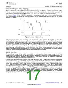
As shown in Figure 18, the UCC28740 operates in a valley-skipping mode (also known as valley-hopping) in
most load conditions to maintain an accurate voltage or current regulation point and still switch on the lowest
available VDS voltage.
Figure 18. Valley-Skipping Mode
Valley-skipping modulates each switching cycle into discrete period durations. During FM operation, the
switching cycles are periods when energy is delivered to the output in fixed packets, where the power-per-cycle
varies discretely with the switching period. During operating conditions when the switching period is relatively
short, such as at high-load and low-line, the average power delivered per cycle varies significantly based on the
number of valleys skipped between cycles. As a consequence, valley-skipping adds additional ripple voltage to
the output with a frequency and amplitude dependent upon the loop-response of the shunt-regulator. For a load
with an average power level between that of cycles with fewer valleys skipped and cycles with more valleys
skipped, the voltage-control loop modulates the FB current according to the loop-bandwidth and toggles between
longer and shorter switching periods to match the required average output power.
Startup Operation
An internal high-voltage startup switch, connected to the bulk-capacitor voltage (VBULK) through the HV pin,
charges the VDD capacitor. This startup switch functions similarly to a current source providing typically 250 µA
to charge the VDD capacitor. When VVDD reaches the 21-V UVLO turnon threshold the controller is enabled, the
converter starts switching, and the startup switch turns off.
Often at initial turnon, the output capacitor is in a fully-discharged state. The first three switching-cycle current
peaks are limited to IPP(min) to monitor for any initial input or output faults with limited power delivery. After these
three cycles, if the sampled voltage at VS is less than 1.33 V, the controller operates in a special startup mode.
In this mode, the primary current peak amplitude of each switching cycle is limited to approximately 0.63 ×
IPP(max) and DMAGCC increases from 0.425 to 0.735. These modifications to IPP(max) and DMAGCC during startup
allows high-frequency charge-up of the output capacitor to avoid audible noise while the demagnetization voltage
is low. Once the sampled VS voltage exceeds 1.38 V, DMAGCC is restored to 0.425 and the primary current peak
resumes as IPP(max). While the output capacitor charges, the converter operates in CC mode to maintain a
constant output current until the output voltage enters regulation. Thereafter, the controller responds to the
condition dictated by the control law. The time to reach output regulation consists of the time the VDD capacitor
charges to 21 V plus the time the output capacitor charges.
Copyright © 2013, Texas Instruments Incorporated
Submit Documentation Feedback
17
Product Folder Links: UCC28740

 TI [ TEXAS INSTRUMENTS ]