UCC28740
SLUSBF3A –JULY 2013–REVISED JULY 2013
www.ti.com
Primary-Side Constant-Current (CC) Regulation
When the load current of the converter increases to the predetermined constant-current limit, operation enters
CC mode. In CC mode, output voltage regulation is lost and the shunt-regulator drives the current and voltage at
FB to minimum. During CC mode, timing information at the VS pin and current information at the CS pin allow
accurate regulation of the average current of the secondary winding. The CV-regulation control law dictates that
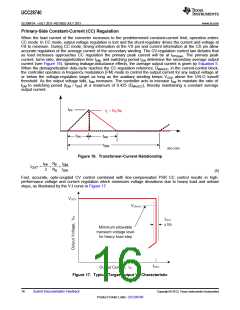
as load increases approaches CC regulation the primary peak current will be at IPP(max). The primary peak
current, turns-ratio, demagnetization time tDM, and switching period tSW determine the secondary average output
current (see Figure 16). Ignoring leakage-inductance effects, the average output current is given by Equation 5.
When the demagnetization duty-cycle reaches the CC-regulation reference, DMAGCC, in the current-control block,
the controller operates in frequency modulation (FM) mode to control the output current for any output voltage at
or below the voltage-regulation target as long as the auxiliary winding keeps VVDD above the UVLO turnoff
threshold. As the output voltage falls, tDM increases. The controller acts to increase tSW to maintain the ratio of
tDM to switching period (tDM / tSW) at a maximum of 0.425 (DMAGCC), thereby maintaining a constant average
output current.
IPP
IS × NS/NP
tON
tDM
tSW
UDG-12203
Figure 16. Transformer-Current Relationship
I
N
t
DM
PP
P
´
I
=
´
OUT
2
N
t
SW
S
(5)
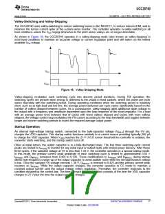
Fast, accurate, opto-coupled CV control combined with line-compensated PSR CC control results in high-
performance voltage and current regulation which minimizes voltage deviations due to heavy load and unload
steps, as illustrated by the V-I curve in Figure 17.
Figure 17. Typical Target Output V-I Characteristic
16
Submit Documentation Feedback
Copyright © 2013, Texas Instruments Incorporated
Product Folder Links: UCC28740

 TI [ TEXAS INSTRUMENTS ]