UCC28740
www.ti.com
SLUSBF3A –JULY 2013–REVISED JULY 2013
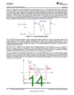
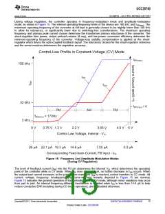
During voltage regulation, the controller operates in frequency-modulation mode and amplitude-modulation
mode, as shown in Figure 15. The internal operating-frequency limits of the device are 100 kHz and fSW(min). The
maximum operating frequency of the converter at full-load is generally chosen to be slightly lower than 100 kHz
to allow for tolerances, or significantly lower due to switching-loss considerations. The maximum operating
frequency and primary peak current chosen determine the transformer primary inductance of the converter. The
shunt-regulator bias power, output preload resistor (if any), and low-power conversion efficiency determine the
minimum-operating frequency of the converter. Voltage-loop stability compensation is applied at the shunt-
regulator which drives the opto-coupled feedback signal. The tolerances chosen for the shunt-regulator reference
and the sense resistors determines the regulation accuracy.
Figure 15. Frequency And Amplitude Modulation Modes
(During CV Regulation)
The level of feedback current (IFB) into the FB pin determines the internal VCL which determines the operating
point of the controller while in CV mode. When IFB rises above 22 µA, no further decrease in fSW occurs. When
the output-load current increases to the point where maximum fSW is reached, control transfers to CC mode. All
current, voltage, frequency, breakpoints, and curve-segment linearity depicted in Figure 15 are nominal.
Figure 15 indicates the general operation of the controller while in CV mode, although minor variations may occur
from part to part. An internal frequency-dithering mechanism is enabled when IFB is less than 14.6 µA to help
reduce conducted EMI (including during CC-mode operation), and is disabled otherwise.
Copyright © 2013, Texas Instruments Incorporated
Submit Documentation Feedback
15
Product Folder Links: UCC28740

 TI [ TEXAS INSTRUMENTS ]