UCC28740
www.ti.com
SLUSBF3A –JULY 2013–REVISED JULY 2013
FUNCTIONAL DESCRIPTION
The UCC28740 is a flyback power-supply controller which provides high-performance voltage regulation using an
optically-coupled feedback signal from a secondary-side voltage regulator. The device provides accurate
constant-current regulation using primary-side feedback. The controller operates in discontinuous-conduction
mode (DCM) with valley-switching to minimize switching losses. The control law scheme combines frequency
with primary peak-current amplitude modulation to provide high conversion efficiency across the load range. The
control law provides a wide dynamic operating range of output power which allows the power-supply designer to
easily achieve less than 30-mW standby power dissipation using a standard shunt-regulator and optocoupler. For
a target of less than 10-mW standby power, careful loss-management design with a low-power regulator and
high-CTR optocoupler is required.
During low-power operating conditions, the power-management features of the controller reduce the device-
operating current at switching frequencies below 32 kHz. At and above this frequency, the UCC28740 includes
features in the modulator to reduce the EMI peak energy of the fundamental switching frequency and harmonics.
A complete low-cost and low component-count charger-solution is realized using a straight-forward design
process.
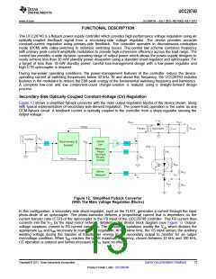
Secondary-Side Optically-Coupled Constant-Voltage (CV) Regulation
Figure 12 shows a simplified flyback convertor with the main output-regulation blocks of the device shown, along
with typical implementation of secondary-side-derived regulation. The power-train operation is the same as any
DCM-flyback circuit. A feedback current is optically coupled to the controller from a shunt-regulator sensing the
output voltage.
Figure 12. Simplified Flyback Convertor
(With The Main Voltage Regulation Blocks)
In this configuration, a secondary-side shunt-regulator, such as the TL431, generates a current through the input
photo-diode of an optocoupler. The photo-transistor delivers a proportional current that is dependent on the
current-transfer ratio (CTR) of the optocoupler to the FB input of the UCC28740 controller. This FB current then
converts into the VCL by the input-mirror network, detailed in the device block diagram (see Figure 1). Output-
voltage variations convert to FB-current variations. The FB-current variations modify the VCL which dictates the
appropriate IPP and fSW necessary to maintain CV regulation. At the same time, the VS input senses the auxiliary
winding voltage during the transfer of transformer energy to the secondary output to monitor for an output
overvoltage condition. When fSW reaches the target maximum frequency, chosen between 32 kHz and 100 kHz,
CC operation is entered and further increases in VCL have no effect.
Copyright © 2013, Texas Instruments Incorporated
Submit Documentation Feedback
13
Product Folder Links: UCC28740

 TI [ TEXAS INSTRUMENTS ]