UCC28070-Q1
SLUSA71A –JULY 2010–REVISED JUNE 2011
www.ti.com
Current Loop Compensation
The UCC28070 incorporates two identical and independent transconductance-type current-error amplifiers (one
for each phase) with which to control the shaping of the PFC input current waveform. The current-error amplifier
(CA) forms the heart of the embedded current control loop of the boost PFC pre-regulator, and is compensated
for loop stability using familiar principles [4, 5]. The output of the CA for phase-A is CAOA, and that for phase-B
is CAOB. Since the design considerations are the same for both, they are collectively referred to as CAOx,
where the "x" may be "A" or "B".
In a boost PFC pre-regulator, the current control loop comprises the boost power plant stage, the current sensing
circuitry, the wave-shape reference, the PWM stage, and the CA with compensation components. The CA
compares the average boost inductor current sensed with the wave-shape reference from the multiplier stage
and generates an output current proportional to the difference.
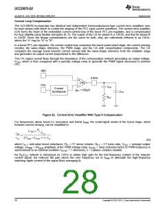
This CA output current flows through the impedance of the compensation network generating an output voltage,
VCAO, which is then compared with a periodic voltage ramp to generate the PWM signal necessary to achieve
PFC.
IMO
CAOx
+
CAx
CSx
CZC
Current
gmc = 100µS
Synthesizer
CPC
RZC
Figure 22. Current Error Amplifier With Type II Compensation
For frequencies above boost LC resonance and below fPWM, the small-signal model of the boost stage, which
includes current sensing, can be simplified to:
RS
Vout ´
vRS
NCT
=
vCA DVRMP ´kSYNC ´ s´ LB
(22)
where LB = mid-value boost inductance, RS = CT sense resistor, NCT = CT turns ratio, VOUT = average output
voltage, ∆VRMP = 4Vpk-pk amplitude of the PWM voltage ramp, kSYNC = ramp reduction factor (if PWM frequency is
synchronized to an external oscillator; kSYNC = 1 otherwise), s = Laplace complex variable
An RZCCZC network is introduced on CAOx to obtain high gain for the low-frequency content of the inductor
current signal, but reduced flat gain above the zero frequency out to fPWM to attenuate the high-frequency
switching ripple content of the signal (thus averaging it).
28
Copyright © 2010–2011, Texas Instruments Incorporated

 TI [ TEXAS INSTRUMENTS ]