UCC21759-Q1
SLUSEB4A – AUGUST 2020 – REVISED DECEMBER 2020
www.ti.com
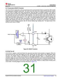
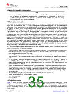
8.3.7 Desaturation (DESAT) Protection
The UCC21759-Q1 implements a fast overcurrent and short circuit protection feature to protect the IGBT module
from catastrophic breakdown during fault. The DESAT pin of the device has a typical 9V threshold with respect
to COM, source or emitter of the power semiconductor. When the input is in floating condition, or the output is
held in low state, the DESAT pin is pulled down by an internal MOSFET and held in LOW state, which prevents
the overcurrent and short circuit fault from false triggering. The internal current source of the DESAT pin is
activated only during the driver ON state, which means the overcurrent and short circuit protection feature only
works when the power semiconductor is in on state. The internal pulldown MOSFET helps to discharge the
voltage of DESAT pin when the power semiconductor is turned off. UCC21759-Q1 features a 200ns internal
leading edge blanking time after the OUTH switches to high state. The internal current source is activated to
charge the external blanking capacitor after the internal leading edge blanking time. The typical value of the
internal current source is 500µA.
VDD
DESAT
DHV
R
+
DESAT Fault
CBLK
+
VDESAT
œ
Control
Logic
COM
Figure 8-5. DESAT Protection
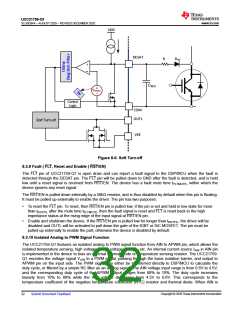
8.3.8 Soft Turn-off
UCC21759-Q1 initiates a soft turn-off when the overcurrent and short circuit protection is triggered. When the
overcurrent and short circuit fault happens, the IGBT transits from the active region to the desaturation region
very fast. The channel current is controlled by the gate voltage and decreasing in a soft manner, thus the
overshoot of the IGBT is limited and prevents the overvoltage breakdown. There is a tradeoff between the
overshoot voltage and short circuit energy. The turn off speed needs to be slow to limit the overshoot voltage,
but the shutdown time should not be too long that the large energy dissipation can breakdown the device. The
400mA soft turn off current of UCC21759-Q1 makes sure the power switches is safely turned off during short
circuit events. The timing diagram of soft turn-off shows in Figure 7-10.
Copyright © 2020 Texas Instruments Incorporated
Submit Document Feedback
31

 TI [ TEXAS INSTRUMENTS ]