UCC21759-Q1
SLUSEB4A – AUGUST 2020 – REVISED DECEMBER 2020
www.ti.com
VDD
D1 D2 D3
OUTH
Control
Circuitry
OUTL
CLMPI
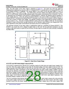
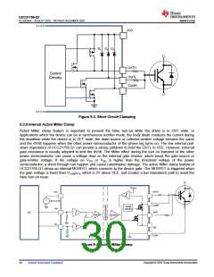
Figure 8-3. Short Circuit Clamping
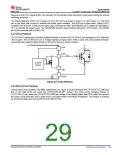
8.3.6 Internal Active Miller Clamp
Active Miller clamp feature is important to prevent the false turn-on while the driver is in OFF state. In
applications which the device can be in synchronous rectifier mode, the body diode conducts the current during
the deadtime while the device is in OFF state, the drain-source or collector-emitter voltage remains the same
and the dV/dt happens when the other power semiconductor of the phase leg turns on. The low internal pull-
down impedance of UCC21759-Q1 can provide a strong pulldown to hold the OUTL to VEE. However, external
gate resistance is usually adopted to limit the dV/dt. The Miller effect during the turn on transient of the other
power semiconductor can cause a voltage drop on the external gate resistor, which boost the gate-source or
gate-emitter voltage. If the voltage on VGS or VGE is higher than the threshold voltage of the power
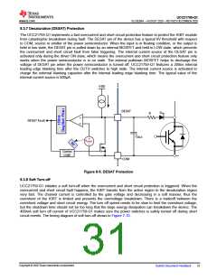
semiconductor, a shoot through can happen and cause catastrophic damage. The active Miller clamp feature of
UCC21759-Q1 drives an internal MOSFET, which connects to the device gate. The MOSFET is triggered when
the gate voltage is lower than VCLMPTH, which is 2V above VEE, and creates a low impedance path to avoid the
false turn on issue.
VCLMPTH
VCC
OUTH
+
3V to 5.5V
IN+
œ
CLMPI
OUTL
Control
Circuitry
µC
MOD
DEMOD
IN-
VEE
COM
VCC
Figure 8-4. Active Miller Clamp
Copyright © 2020 Texas Instruments Incorporated
30
Submit Document Feedback

 TI [ TEXAS INSTRUMENTS ]