TPS7H5005-SEP, TPS7H5006-SEP, TPS7H5007-SEP, TPS7H5008-SEP
SLVSGG1 – FEBRUARY 2022
www.ti.com
8.3.8.1 Internal Oscillator Mode
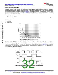
A resistor from the RT pin to AVSS sets the switching frequency of the device. The TPS7H500x-SEP controller
has a switching frequency range of 100 kHz to 2 MHz. In internal oscillator mode, the RT pin must be populated
or the controller will not perform any switching. Equation 7 shows the calculation determining the RT value for a
desired switching frequency. The curve in Figure 8-7 shows the RT value that corresponds to a given switching
frequency for the TPS7H500x-SEP.
112000
RT =
19.7
fsw
(7)
where:
•
•
RT is in kΩ
fsw is in kHz
1200
1000
800
600
400
200
0
0
200 400 600 800 1000 1200 1400 1600 1800 2000
Switching Frequency (kHz)
Figure 8-7. RT vs Switching Frequency
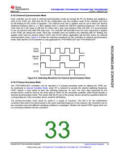
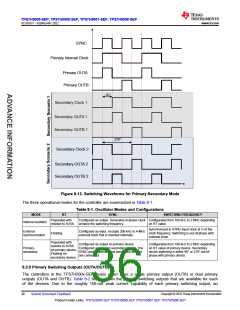
In this mode, the SYNC pin is configured as an output and produces a clock signal with a frequency that is
twice that of the switching frequency set by RT. As such, this clock signal has a range of 200 kHz to 4 MHz.
This SYNC output clock signal is in phase with the switching frequency of the device. Figure 8-8 shows typical
waveforms for the controllers in this mode of operation. Note that the OUTB waveform is only applicable for
TPS7H5005-SEP and TPS7H5008-SEP.
SYNC
(Output)
Internal
Clock
OUTA
OUTB
Figure 8-8. Switching Waveforms for Internal Oscillator Mode
Copyright © 2022 Texas Instruments Incorporated
32
Submit Document Feedback
Product Folder Links: TPS7H5005-SEP TPS7H5006-SEP TPS7H5007-SEP TPS7H5008-SEP

 TI [ TEXAS INSTRUMENTS ]