TPS7H5005-SEP, TPS7H5006-SEP, TPS7H5007-SEP, TPS7H5008-SEP
www.ti.com
SLVSGG1 – FEBRUARY 2022
8.3.8.2 External Synchronization Mode
Each controller can be used in external synchronization mode by leaving the RT pin floating and applying a
clock to the SYNC pin. Note than the RT pin configuration sets the oscillator mode of the controller and must
be left floating for this mode of operation. The external clock that is applied must be set to twice the desired
switching frequency (that is, a 1-MHz applied clock is needed for 500-kHz switching frequency). The external
clock must be in the range of 200 kHz to 4 MHz with a duty cycle between 40% and 60%. It is recommended
to use an external clock with 50% duty cycle. The controller will internally invert the clock signal that is applied
at the SYNC pin during this mode. Since the controller does not perform any switching with RT floating, the
applied clock must be present before OUTA and OUTB (where applicable) will become active for external
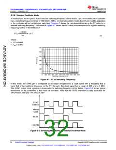
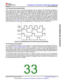
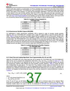
synchronization mode. Figure 8-9 shows the switching waveforms for the controllers in external synchronization
mode. Note that the OUTB waveform is only applicable for TPS7H5005-SEP and TPS7H5008-SEP.
SYNC
(Input)
Internal
Clock
OUTA
OUTB
Figure 8-9. Switching Waveforms for External Synchronization Mode
8.3.8.3 Primary-Secondary Mode
Two TPS7H500x-SEP controllers can be operated in a primary-secondary mode by utilizing the SYNC pin.
As mentioned in Internal Oscillator Mode, when RT is selected to provide the desired switching frequency,
SYNC outputs a clock signal at twice the switching frequency. As such, the clock input generated by the
primary device could be used as the clock input at SYNC for the secondary controller, which would operate in
external synchronization mode. This means that the RT pin of the primary device should be populated while the
corresponding pin of the secondary device would be left floating.
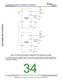
The primary-secondary mode would be useful in a couple of scenarios. The first is for two independent
converters that need to be synchronized to the same switching frequency. In this instance, the converters can be
two converters can have different operating conditions or topologies. Besides the shared SYNC signal, there are
no connections between the two converters.
Copyright © 2022 Texas Instruments Incorporated
Submit Document Feedback
33
Product Folder Links: TPS7H5005-SEP TPS7H5006-SEP TPS7H5007-SEP TPS7H5008-SEP

 TI [ TEXAS INSTRUMENTS ]