TPS55340
SLVSBD4 –MAY 2012
www.ti.com
DESIGN GUIDE-STEP-BY-STEP DESIGN PROCEDURE OF BOOST CONVERTER
The following section provides a step-by-step design approach for configuring the TPS55340 as a voltage
regulating boost converter, as shown in Figure 15. When configured as SEPIC or flyback converter, a different
design approach is required. A design example of SEPIC converter is provided in the next section.
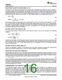
100 pF
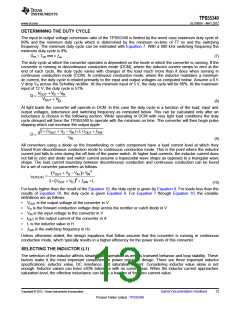
Figure 15. Boost Converter Application Schematic
A few parameters must be known in order to start the design process. These parameters are typically determined
at the system level. For this example, we will start with the following known parameters:
Table 1. Key Parameters of Boost Converter Example
PARAMETER
VALUE
Output Voltage
Input Voltage
24 V
5 V to 12 V
800 mA
Maximum Output Current
Transient Response 50% load step (ΔVOUT = 3%) 960 mV
Output Voltage Ripple (0.5% of VOUT
)
120 mV
SELECTING THE SWITCHING FREQUENCY (R4)
The first step is to decide on a switching frequency for the regulator. There are tradeoffs to consider for a higher
or lower switching frequency. A higher switching frequency allows for lower valued inductor and smaller output
capacitors leading to the smallest solution size. A lower switching frequency will result in a larger solution size
but better efficiency. The user will typically set the frequency for the minimum tolerable efficiency to avoid
excessively large external components.
A switching frequency of 600 kHz is a good trade-off between efficiency and solution size. The appropriate
resistor value is found from the resistance versus frequency graph of Figure 5, or calculated using Equation 1.
R4 is calculated to be 78.4 kΩ and the nearest standard value resistor of 78.7 kΩ is selected. A resistor must be
placed from the FREQ pin to ground, even if an external oscillation is applied for synchronization.
12
Submit Documentation Feedback
Copyright © 2012, Texas Instruments Incorporated
Product Folder Link(s) :TPS55340

 TI [ TEXAS INSTRUMENTS ]