TPS5430
www.ti.com
SLVS632–JANUARY 2006
Output Filter Componts
Two components need to be selected for the output filter, L1 and C2. Since the TPS5430 is an internally
compensated device, a limited range of filter component types and values can be supported.
Inductor Selection
To calculate the minimum value of the output inductor, use Equation 4:
V
V
OUT(MAX)
IN(MAX)
OUT
L
MIN
V
K
I
IN(max)
IND
SW
(4)
KIND is a coefficient that represents the amount of inductor ripple current relative to the maximum output current.
Three things need to be considered when determining the amount of ripple current in the inductor: the peak to
peak ripple current affects the output ripple voltage amplitude, the ripple current affects the peak switch current
and the amount of ripple current determines at what point the circuit will become discontinuous. For designs
using the TPS5430, KIND of 0.2 to 0.3 yields good results. Low output ripple voltages can be obtained when
paired with the proper output capacitor, the peak switch current will be well below the current limit set point and
relatively low load currents can be sourced before dicontinuous operation.
For this design example use KIND = 0.2 and the minimum inductor value is calculated to be 12.5µH. The next
highest standard value is 15 µH, which is used in this design.
For the output filter inductor it is important that the RMS current and saturation current ratings not be exceeded.
The RMS inductor current can be found from Equation 5:
2
ǓV
V
V
IN(MAX)
OUT
OUT
1
12
I2OUT(MAX)
I
ǒ
)
L(RMS)
V
L
F
0.8
SW
IN(MAX)
OUT
(5)
(6)
and the peak inductor current can be determined with Equation 6:
V
V
V
IN(MAX)
OUT
OUT
I
ǒ
I
)
L(PK)
OUT(MAX)
1.6 V
L
F
IN(MAX)
OUT
SW
For this design, the RMS inductor current is 3.003 A, and the peak inductor current is 3.31 A. The chosen
inductor is a Sumida CDRH104R-150 15µH. It has a saturation current rating of 3.4 A and a RMS current rating
of 3.6 A, easily meeting these requirements. A lesser rated inductor could be used, however this device was
chosen because of its low profile component height. In general, inductor values for use with the TPS5430 are in
the range of 10 µH to 100 µH.
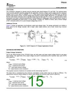
Capacitor Selection
The important design factors for the output capacitor are dc voltage rating, ripple current rating, and equivalent
series resistance (ESR). The dc voltage and ripple current ratings cannot be exceeded. The ESR is important
because along with the inductor ripple current it determines the amount of output ripple voltage. The actual value
of the output capacitor is not critical, but some practical limits do exist. Consider the relationship between the
desired closed loop crossover frequency of the design and LC corner frequency of the output filter. Due to the
design of the internal compensation, it is desirable to keep the closed loop crossover frequency in the range 3
kHz to 30 kHz as this frequency range has adequate phase boost to allow for stable operation. For this design
example, it is assumed that the intended closed loop crossover frequency will be between 2590 Hz and 24 kHz
and also below the ESR zero of the output capacitor. Under these conditions the closed loop crossover
frequency will be related to the LC corner frequency by:
2
f
LC
f
CO
85 V
OUT
(7)
And the desired output capacitor value for the output filter to:
13

 TI [ TEXAS INSTRUMENTS ]