TPS54560
www.ti.com
SLVSBN0 –MARCH 2013
DETAILED DESCRIPTION (continued)
æ
ç
è
ö
÷
ø
s
1+
1+
2p´ fZ
VOUT
= Adc ´
VC
æ
ç
è
ö
÷
ø
s
2p´ fP
(9)
Adc = gmps ´ RL
(10)
1
f
=
P
C
´R ´ 2p
L
OUT
(11)
(12)
1
f
=
Z
C
´R
´ 2p
OUT
ESR
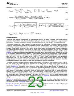
Small Signal Model for Frequency Compensation
The TPS54560 uses a transconductance amplifier for the error amplifier and supports three of the commonly-
used frequency compensation circuits. Compensation circuits Type 2A, Type 2B, and Type 1 are shown in
Figure 33. Type 2 circuits are typically implemented in high bandwidth power-supply designs using low ESR
output capacitors. The Type 1 circuit is used with power-supply designs with high-ESR aluminum electrolytic or
tantalum capacitors. Equation 13 and Equation 14 relate the frequency response of the amplifier to the small
signal model in Figure 33. The open-loop gain and bandwidth are modeled using the RO and CO shown in
Figure 33. See the application section for a design example using a Type 2A network with a low ESR output
capacitor.
Equation 13 through Equation 22 are provided as a reference. An alternative is to use WEBENCH software tools
to create a design based on the power supply requirements.
V
O
R1
FB
Type 2A
Type 2B
Type 1
gm
ea
R
COMP
Vref
C2
R3
C1
R3
R2
C2
C
O
O
C1
Figure 33. Types of Frequency Compensation
Copyright © 2013, Texas Instruments Incorporated
Submit Documentation Feedback
19
Product Folder Links: TPS54560

 TI [ TEXAS INSTRUMENTS ]