TPS54560
SLVSBN0 –MARCH 2013
www.ti.com
DETAILED DESCRIPTION (continued)
Simple Small Signal Model for Peak Current Mode Control
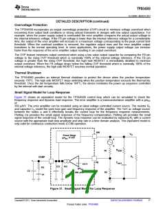
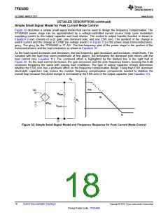
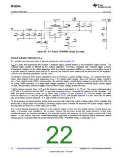
Figure 32 describes a simple small signal model that can be used to design the frequency compensation. The
TPS54560 power stage can be approximated by a voltage-controlled current source (duty cycle modulator)
supplying current to the output capacitor and load resistor. The control to output transfer function is shown in
Equation 9 and consists of a dc gain, one dominant pole, and one ESR zero. The quotient of the change in
switch current and the change in COMP pin voltage (node c in Figure 31) is the power stage transconductance,
gmPS. The gmPS for the TPS54560 is 17 A/V. The low-frequency gain of the power stage is the product of the
transconductance and the load resistance as shown in Equation 10.
As the load current increases and decreases, the low-frequency gain decreases and increases, respectively. This
variation with the load may seem problematic at first glance, but fortunately the dominant pole moves with the
load current (see Equation 11). The combined effect is highlighted by the dashed line in the right half of
Figure 32. As the load current decreases, the gain increases and the pole frequency lowers, keeping the 0-dB
crossover frequency the same with varying load conditions. The type of output capacitor chosen determines
whether the ESR zero has a profound effect on the frequency compensation design. Using high ESR aluminum
electrolytic capacitors may reduce the number frequency compensation components needed to stabilize the
overall loop because the phase margin is increased by the ESR zero of the output capacitor (see Equation 12).
V
O
Adc
VC
R
ESR
fp
R
L
gm
ps
C
OUT
fz
Figure 32. Simple Small Signal Model and Frequency Response for Peak Current Mode Control
18
Submit Documentation Feedback
Copyright © 2013, Texas Instruments Incorporated
Product Folder Links: TPS54560

 TI [ TEXAS INSTRUMENTS ]