TPS51640A, TPS59640, TPS59641
SLUSAQ2 –JANUARY 2012
www.ti.com
V ´ dT
L =
I
P-P
(7)
In this equation,
V = VIN-MAX – VHFM = 19. 1V; dT = VHFM / (F x VIN-MAX) = 150 ns; Ipp = 9.4A. So, calculating, L = 0.304 µH.
An inductance value of 0.36 µH is chosen as this is a commonly used inductor for VCORE application. The
inductor must not saturate during peak loading conditions.
I
æ
ç
ö
÷
CC max
(
I
)
P-P
I
=
+
´1.2 = 43.2A
SAT
ç
è
÷
ø
N
2
PHASE
(8)
The factor of 1.2 allows for current sensing and current limiting tolerances; the factor of 1.25 is the Intel 25%
momentary OCP requirement.
The chosen inductor should have the following characteristics:
•
An inductance to current curve ratio equal to 1 (or as close possible). Inductor DCR sensing is based on the
idea L/DCR is approximately a constant through the current range of interest.
•
•
•
Either high saturation or soft saturation.
Low DCR for improved efficiency, but at least 0.7 mΩ for proper signal levels.
DCR tolerance as low as possible for load-line accuracy.
For this application, a 0.36-µH, 0.825-mΩ inductor is chosen. Because the per phase current for GPU is same as
CPU, the same inductor for GPU channel is chosen.
Step Five: Determine current sensing method.
The TPS51640A, TPS59640, and TPS59641 support both resistor sensing and inductor DCR sensing. Inductor
DCR sensing is chosen. For resistor sensing, substitute the resistor value (0.75 mΩ recommended for a 3-phase
94-A application) for RCS in the subsequent equations and skip Step Four.
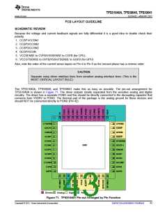
Step Six: Design the thermal compensation network and selection of OCP.
In most designs, NTC thermistors are used to compensate thermal variations in the resistance of the inductor
winding. This winding is generally copper, and so has a resistance coefficient of 3900 PPM/°C. NTC thermistors,
on the other hand, have very non-linear characteristics and need two or three resistors to linearize them over the
range of interest. The typical DCR circuit is shown in Figure 70.
L
RDCR
I
RSEQU
RNTC
RSERIES
RPAR
CSENSE
CSP
CSN
UDG-11039
Figure 70. Typical DCR Sensing Circuit
In this circuit, the voltage across the CSENSE exactly equals the voltage across RDCR when Equation 9 is true.
40
Submit Documentation Feedback
Copyright © 2012, Texas Instruments Incorporated

 TI [ TEXAS INSTRUMENTS ]