TPS51640A, TPS59640, TPS59641
www.ti.com
SLUSAQ2 –JANUARY 2012
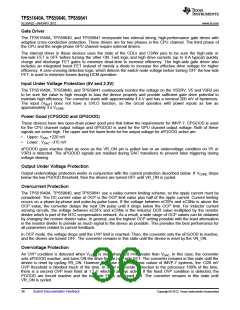
Over Temperature Protection
Two types of thermal protection are provided in these devices:
•
•
VR_HOT
Thermal Shutdown
VR_HOT
The VR_HOT signal is an Intel-defined open-drain signal that is used to protect the VCORE power chain. To use
VR_HOT, place an NTC thermistor at the hottest area of the CPU channel and connect it from CTHERM pin to
GND. Similarly for GPU channel, place the NTC thermistor at the hottest area and connect it from GTHERM to
GND. Also, connect a resistor from VREF to GTHERM and CTHERM. As the temperature increases, the
xTHERM voltage drops below the THERM threshold, VR_HOT is activated. A small capacitor may be connected
to the xTHERM pins for high frequency noise filtering.
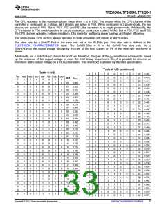
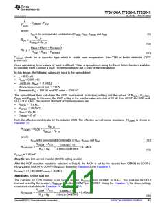
lists the thermal zone register bits based on the xTHERM pin voltage.
Table 5. Thermal Zone Register Bits
OUTPUT IS
SHUTDOWN
VR_HOT
ASSERTED
xTHERM THRESHOLD VOLTAGE FOR THE TEMPERATURE
ZONE REGISTER BITS TO BE ASSERTED.
SVID ALERT ASSERTED
b7
b6
b5
b4
b3
b2
b1
b0
410 mV
455 mV
458 mV
523 mV
559 mV
598 mV
638 mV 680 mV
783 mV
Thermal Shutdown
When the xTHERM pin voltage continues to drop even after VR_HOT is asserted, the drivers turn OFF and the
output is shutdown. These devices also have an internal temperature sensor. When the temperature reaches a
nominal 155°C, the device shuts down until the temperature cools approximately 20°C. Then, the circuit can be
re-started by cycling VR_ON.
Current Monitor, IMON
The TPS51640A, TPS59640, and TPS59641 includes a current monitor (IMON) function each for CPU channel
and GPU channel. The current monitor puts out an analog voltage proportional to the output current on the
xIMON pins.
The current monitor function is tied with the OCP selection resistors. The RCOCP and RGOCP are resistors to GND
from COCP-I and GOCP-I respectively to select the OCP levels. RCIMON is the resistor from CIMON to COCP-I to
set the CIMON gain. Similarly, RGIMON is the resistor from GIMON to GOCP-I to set the GIMON gain.
The calculation for the CIMON voltage is shown in Equation 2. The calculation for the GIMON voltages is shown
in Equation 3.
æ
ç
è
ö
÷
ø
R
CIMON
V
= A ´ 1+
´
V
CCSn
CIMON
CS
å
R
COCP
(2)
æ
ç
è
ö
R
GIMON
V
= A ´ 1+
´ V
÷
GCS
GIMON
CS
R
GOCP
ø
where
•
•
•
ACS is given in the ELECTRICAL CHARACTERISTICS table
Σ VCCS is the sum of the DC voltages at the inputs to the CPU channel current sense amplifiers
VGCS is the DC voltage at the GPU channel current sense amplifier
(3)
For the current monitor function to be stable, connect a 220-nF capacitor from CIMON and GIMON to GND.
Copyright © 2012, Texas Instruments Incorporated
Submit Documentation Feedback
37

 TI [ TEXAS INSTRUMENTS ]