TPS51640A, TPS59640, TPS59641
SLUSAQ2 –JANUARY 2012
www.ti.com
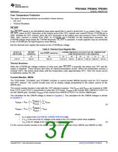
Setting the Maximum Processor Current (ICC(max)
)
The TPS51640 controller allows the user to set the maximum processor current with the multi-function pins
CF-IMAX and GF-IMAX. The voltage on the CF-IMAX and GF-IMAX at start-up sets the maximum processor
current (ICC(max)) for CPU and GPU respectively.
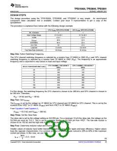
The RCF and RGF are resistors to GND from CF-IMAX and GF-IMAX respectively to select the frequency setting.
RCIMAX is the resistor from VREF to CF-IMAX and RGIMAX is the resistor from VREF to GF-IMAX.
Equation 4 describes the setting the ICC(max) for the CPU channel and Equation 5 describes the setting the
ICC(max) for the GPU channel.
æ
ç
è
ö
÷
ø
R
CF
I
= 255´
CC max CPU
)
(
R
+ R
CF
CIMAX
(4)
(5)
æ
ç
è
ö
÷
ø
R
GF
I
= 255´
CC max GPU
)
(
R
+ R
GIMAX
GF
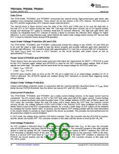
Internal Driver Bypass Mode
The controller can be configured to operate in internal driver bypass mode for use with DrMOS type devices and
driver-integrated PowerBlock devices. Consider the following items when designing for operation in this mode.
•
•
•
•
•
Tie CSW2, CSW1 to V5DRV.
CDL1 becomes the PWM input to the Phase 1 DrMOS device (or external driver)
CDL2 becomes the PWM input to the Phase 2 DrMOS device (or external driver)
CSKIP pin becomes the input to the SKIP/FCCM pin of the DrMOS device (or external driver)
The Phase-2 and Phase-3 DrMOS device (or the external driver) must be configured in FCCM mode.
38
Submit Documentation Feedback
Copyright © 2012, Texas Instruments Incorporated

 TI [ TEXAS INSTRUMENTS ]