TPS1HC100-Q1
ZHCSLK6A –JULY 2021 –REVISED DECEMBER 2021
www.ti.com.cn
9.2.3 Application Curves
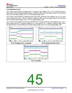
图 9-5 shows a test example of charging a 470-μF capacitor. Test conditions: VBB = 13.5 V, input is from low to
high, load is a 470-µF capacitive load, ILIM pin is shorted to GND. CH4 is the output current. CH3 is the input
step. CH2 is the output voltage, VOUT. CH1 is the supply voltage, VBB
图 9-6 shows a test example of a enable into short-circuit inrush current limit. Test conditions: VBB= 13.5 V, input
is low to high, load is 5 µH + 100 mΩ, ILIM pin is shorted to GND. CH4 is the output current. CH3 is the input
step. CH2 is the output voltage, VOUT. CH1 is the supply voltage, VBB
图 9-7 shows a test example of a load step from 500 mA to 3 A back to 500 mA. Test conditions: VBB= 13.5 V,
input is high, load is 6.75 Ωand then changed to 4.5 Ωthen back to 6.75 Ω, ILIM pin is shorted to GND. CH4 is
the output current. CH3 is the SNS pin. CH2 is the output voltage, VOUT. CH1 is the supply voltage, VBB
图9-5. Charging a 470-μF Capacitor
图9-6. Enable into Short Circuit
图9-7. Load Step
Copyright © 2022 Texas Instruments Incorporated
Submit Document Feedback
45
Product Folder Links: TPS1HC100-Q1

 TI [ TEXAS INSTRUMENTS ]