TPS1HC100-Q1
ZHCSLK6A –JULY 2021 –REVISED DECEMBER 2021
www.ti.com.cn
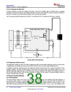
TI recommends RPROT = 5 kΩto ensure the current going into the digital pins (EN, DIAG_EN, LATCH) is limited.
TI recommends a 1-kΩresistor and 200-V, 0.2-A diode (BAS21 for example) for the GND network.
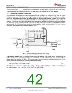
9.2.2.1 Dynamically Changing Current Limit
The current limit threshold is able to be changed dynamically by altering the resistance going from the current
limit pin to the ground of the device on the fly. This alteration allows the system to have a different current limit
for start-up, when there can be significant inrush current, and during normal operation. The way this is commonly
done is by putting two resistors in parallel on the ILIM pin and having a switch to enable or disable one of the
resistors. This set-up can be seen in the figure below. Alternatively, a digital potentiometer can be used to adjust
the impedance on the ILIM pin on the fly. Care must be taken so that the capacitance on the ILIM pin is below
approximately 100 pF because it can cause the current regulation loop to become unstable. The most common
application where this feature is useful is capacitive loads.
VBAT
VBB
Smart High Side Switch
EN
Gate Driver
KCL
KCL (RILIM1 + RILIM2
RILIM1 RILIM2
)
ILIM1
=
ILIM2
=
SW
RILIM
ILIM
Current Limiting
Circuit
(VBB – VOUT
RLOAD
)
INOM
=
VOUT
RILIM2
RILIM1
CLOAD
GND
RLOAD
ILIM = CLOAD x dVDS/dt
图9-2. Dynamic Changing Current Limit Setup
In a capacitive charging case, the initial current to charge the capacitor is the inrush current. Depending on the
system requirements, dynamically changing the current limit can help either charge up a capacitor faster or
charge up a larger capacitor. To allow a higher inrush level of current through in the beginning, the switch can be
closed making the current limit be according to the equation below.
ILIM2 = KCL(RILIM1 + RILIM2) / (RILIM1 × RILIM2
)
(15)
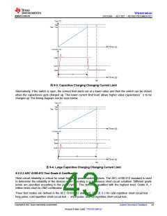
When the inrush event is over and the output voltage is charged up, the switch opens and the current limit is just
the RILIM1 equivalent level. This timing can be seen in the figure below.
Copyright © 2022 Texas Instruments Incorporated
42
Submit Document Feedback
Product Folder Links: TPS1HC100-Q1

 TI [ TEXAS INSTRUMENTS ]