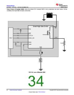
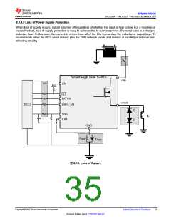
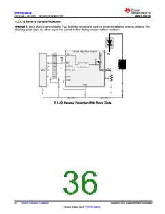
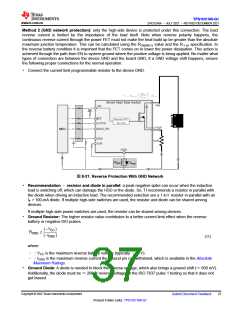
TPS1HC100-Q1
ZHCSLK6A –JULY 2021 –REVISED DECEMBER 2021
www.ti.com.cn
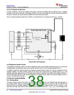
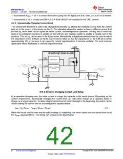
8.3.4.11 Protection for MCU I/Os
In many conditions, such as the negative ISO pulse, or the loss of battery with an inductive load, a negative
potential on the device GND pin can damage the MCU I/O pins (more likely, the internal circuitry connected to
the pins). Therefore, the serial resistors between MCU and HSS are required.
Also, for proper protection against loss of GND, TI recommends 5-kΩresistance for the RPROT resistors.
Smart High Side Switch
VBB
5k
EN
5V
5k
5k
FLT
Reverse FET
Turn On
LATCH
5k
VOUT
MCU
DIAG_EN
5k
SNS
ILIM
Load
GND
RGND
DGND
图8-22. MCU I/O Protections
8.3.5 Diagnostic Enable Function
The diagnostic enable pin, DIAG_EN, offers multiplexing of the microcontroller diagnostic input for current sense
or digital status, by sharing the same sense resistor and ADC line or I/O port among multiple devices.
In addition, during the output-off period, the diagnostic disable function lowers the current consumption for the
standby condition. The three working modes in the device are normal mode (IQ), standby mode (ISTBY), and
standby mode with diagnostic (IDIA). If off-state power saving is required in the system, the standby current is <
500 nA with DIAG_EN low. If the off-state diagnostic is required in the system, the typical standby current is
around 1 mA with DIAG_EN high.
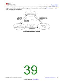
8.4 Device Functional Modes
8.4.1 Working Mode
The three working modes in the device are normal mode, standby mode, and standby mode with diagnostic. If
an off-state power saving is required in the system, the standby current is less than 500 nA with EN and
DIAG_EN low. If an off-state diagnostic is required in the system, the typical standby current is around 1.2 mA
with DIAG_EN high. Note that to enter standby mode requires IN low and t > tSTBY. tSTBY is the standby-mode
Copyright © 2022 Texas Instruments Incorporated
38
Submit Document Feedback
Product Folder Links: TPS1HC100-Q1

 TI [ TEXAS INSTRUMENTS ]