ꢀ
ꢁꢂ
ꢃ
ꢄꢄ
ꢅ
ꢆꢇ
www.ti.com
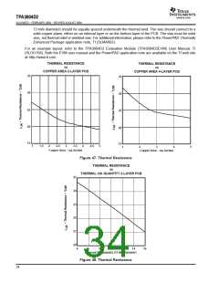
SLOS407D − FEBRUARY 2003 − REVISED AUGUST 2004
Load
RC Low-Pass Filters
RFILT
AP Analyzer Input
CANA
RANA
CFILT
VL= V
IN
RL
VOUT
RFILT
CANA
RANA
CFILT
To APA
GND
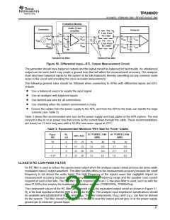
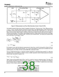
Figure 51. Measurement Low-Pass Filter Derivation Circuit—Class-D APAs
The transfer function for this circuit is shown in equation (10) whereω = R , R = R R
C
and C
EQ
O
EQ EQ EQ
FILT
ANA
= (C
+ C
). The filter frequency should be set above f
, the highest frequency of the measurement
FILT
ANA
MAX
bandwidth, to avoid attenuating the audio signal. Equation (11) provides this cutoff frequency, f . The value of
C
R
must be chosen large enough to minimize current that is shunted from the load, yet small enough to
FILT
minimize the attenuation of the analyzer-input voltage through the voltage divider formed by R
and R
.
FILT
ANA
A rule of thumb is that R
error to less than 1% for R
should be small (~100 Ω) for most measurements. This reduces the measurement
FILT
≥ 10 kΩ.
ANA
R
ANA
ǒ Ǔ
R
)R
V
ANA
FILT
OUT
+
ǒ Ǔ
V
w
IN
1 ) jǒ Ǔ
w
O
(10)
Ǹ
f
+ 2 f
C
MAX
(11)
An exception occurs with the efficiency measurements, where R
must be increased by a factor of ten to
FILT
reduce the current shunted through the filter. C
must be decreased by a factor of ten to maintain the same
FILT
cutoff frequency. See Table 2 for the recommended filter component values.
Once f is determined and R is selected, the filter capacitance is calculated using equation (11). When the
C
FILT
calculated value is not available, it is better to choose a smaller capacitance value to keep f above the minimum
C
desired value calculated in equation (12).
1
C
+
FILT
2p f R
C
FILT
(12)
based on common component values. The value of f
C
Table 4 shows recommended values of R
and C
FILT
FILT
was originally calculated to be 28 kHz for an f
of 20 kHz. C
, however, was calculated to be 57000 pF,
MAX
FILT
but the nearest values of 56000 pF and 51000 pF were not available. A 47000 pF capacitor was used instead,
and f is 34 kHz, which is above the desired value of 28 kHz.
C
Table 4. Typical RC Measurement Filter Values
MEASUREMENT
Efficiency
All other measurements
R
C
FILT
FILT
1 000 Ω
100 Ω
5 600 pF
56 000 pF
38

 TI [ TEXAS INSTRUMENTS ]