www.ti.com
ꢀ ꢁꢂ ꢃꢄꢄ ꢅꢆ ꢇ
SLOS407D − FEBRUARY 2003 − REVISED AUGUST 2004
Evaluation Module
Audio Power
Amplifier
Generator
Analyzer
Low−Pass
RC Filter
CIN
CIN
RGEN
RIN
RIN
ROUT
ROUT
RANA
CANA
RL
VGEN
Low−Pass
RC Filter
RGEN
RANA
CANA
Twisted-Pair Wire
Twisted-Pair Wire
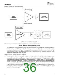
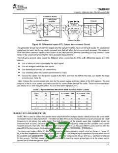
Figure 50. Differential Input—BTL Output Measurement Circuit
The generator should have balanced outputs and the signal should be balanced for best results. An unbalanced
output can be used, but it may create a ground loop that will affect the measurement accuracy. The analyzer
must also have balanced inputs for the system to be fully balanced, thereby cancelling out any common mode
noise in the circuit and providing the most accurate measurement.
The following general rules should be followed when connecting to APAs with differential inputs and BTL
outputs:
D
D
D
D
D
Use a balanced source to supply the input signal.
Use an analyzer with balanced inputs.
Use twisted-pair wire for all connections.
Use shielding when the system environment is noisy.
Ensure the cables from the power supply to the APA, and from the APA to the load, can handle the large
currents (see Table 3).
Table 3 shows the recommended wire size for the power supply and load cables of the APA system. The real
concern is the dc or ac power loss that occurs as the current flows through the cable. These recommendations
are based on 12-inch long wire with a 20-kHz sine-wave signal at 25°C.
Table 3. Recommended Minimum Wire Size for Power Cables
P
(W)
R
(Ω)
DC POWER LOSS
(MW)
AC POWER LOSS
(MW)
OUT
L
AWG SIZE
10
4
18
18
22
22
22
22
28
28
16
3.2
2.0
1.5
40
8.0
8.0
6.1
18
42
8.5
8.1
6.2
2
4
3.7
2.1
1.6
1
8
< 0.75
8
CLASS-D RC LOW-PASS FILTER
An RC filter is used to reduce the square-wave output when the analyzer inputs cannot process the pulse-width
modulated class-D output waveform. This filter has little effect on the measurement accuracy because the cutoff
frequency is set above the audio band. The high frequency of the square wave has negligible impact on
measurement accuracy because it is well above the audible frequency range and the speaker cone cannot
respond at such a fast rate. The RC filter is not required when an LC low-pass filter is used, such as with the
class-D APAs that employ the traditional modulation scheme (TPA032D0x, TPA005Dxx).
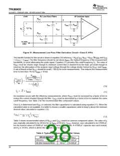
The component values of the RC filter are selected using the equivalent output circuit as shown in Figure 51.
R is the load impedance that the APA is driving for the test. The analyzer input impedance specifications should
L
be available and substituted for R
and C
. The filter components, R
and C
, can then be derived
ANA
ANA
FILT
FILT
for the system. The filter should be grounded to the APA near the output ground pins or at the power supply
ground pin to minimize ground loops.
37

 TI [ TEXAS INSTRUMENTS ]