TMS320TCI6487
TMS320TCI6488
Communications Infrastructure Digital Signal Processor
SPRS358F–APRIL 2007–REVISED AUGUST 2008
www.ti.com
•
Secure ROM Boot
On secure devices, all C64x+ Megamodule Cores are released from reset and begin executing from
secure ROM. Software in the secure ROM will free up internal RAM pages, after which C64x+
Megamodule Core 0 will initiate the boot process as in option 2 and the other C64x+ Megamodule
Cores will wait. The C64x+ Megamodule Core 0 will perform any authentication and decryption
required on the bootloaded image prior to releasing the other C64x+ Megamodule Cores to begin
execution. After the secure loading is complete, the C64x+ Megamodule Core 0 will release the other
C64x+ Megamodule Cores. Then C64x+ Megamodule Core 0 begins execution from the entry address
defined in the boot table. The C64x+ Megamodule Core 1 and 2 begin execution from what is stored in
the magic address. When l2_config is 1, the magic address for both C64x+ Megamodule Core 1 and
C64x+ Megamodule Core 2 is 8FFFFC. When l2_config is 0, the magic address for C64x+
Megamodule Core 1 is 0x8FFFFC and the magic address for C64x+ Megamodule Core 2 is
0x87FFFC.
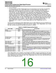
The boot process performed by C64x+ Megamodule Core 0 in public ROM boot and secure ROM boot are
determined by the BOOTMODE[3:0] value in the DEVSTAT register. C64x+ Megamodule Core 0 reads
this value, and then executes the associated boot process in software.
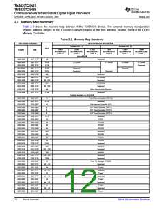
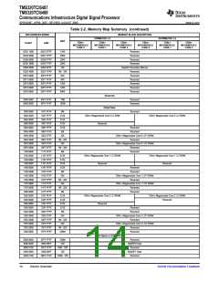
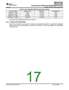
Table 2-3. TCI6487/8 Supported Boot Modes
MODE NAME
BOOTMODE[3:0]
0000b
DESCRIPTION
No Boot (BOOTMODE[3:0] = 0000b)
No Boot
I2C Master Boot A
0001b
Slave I2C address is 0x50. C64x+ Megamodule Core 0 configures I2C, acts as a
master to the I2C bus and copies data from an I2C EEPROM or a device acting as an
I2C slave to the DSP using a predefined boot table format. The destination address
and length are contained within the boot table. After boot table copy is complete, the
C64x+ Megamodule Core 0 brings the other C64x+ Megamodule Cores out of reset
by setting to 1 the EVTPULSE4 bit (bit 4) of the C64x+ Megamodule Core EVTASRT
register.
I2C Master Boot B
I2C Slave Boot
0010b
0011
Similar to I2C boot A except the slave I2C address is 0x51.
The C64x+ Megamodule Core 0 configures I2C and acts as a slave and will accept
data and code section packets through the I2C interface. It is required that an I2C
master in present in the system.
EMAC Master Boot
EMAC Slave Boot
0100b
0101b
0110b
TI Ethernet Boot, C64x+ Megamodule Core 0 configures EMAC0 and EDMA, if
required, and brings the code image into the internal on-chip memory via the protocol
defined by the boot method (EMAC bootloader). After initializing the on-chip memory
to the known state, C64x+ Megamodule Core 0 brings the other C64x+ Megamodule
Cores out of reset.
EMAC Forced-Mode Boot
Reserved
0111b
1000b
1001b
1010b
1011b
Reserved
Serial RapidIO Boot (Config 0)
Serial RapidIO Boot (Config 1)
Serial RapidIO Boot (Config 2)
Serial RapidIO Boot (Config 3)
The C64x+ Megamodule Core 0 configures the SRIO and an external host loads the
application via SRIO peripheral, using directIO protocol. A doorbell interrupt is used to
indicate that the code has been loaded. For more details on the Serial RapidIO
configurations, see Table 2-4.
C64x+ Megamodule Core 0 configures Serial RapidIO and EDMA, if required, and brings the code image
into the internal on-chip memory via the protocol defined by the boot method (SRIO bootloader) and then
C64x+ Megamodule Core 0 brings the other C64x+ Megamodule Cores out of reset. Note that SRIO boot
modes are only supported on port 0.
16
Device Overview
Submit Documentation Feedback

 TI [ TEXAS INSTRUMENTS ]