ꢀ ꢁ ꢂ ꢃ ꢄꢅ ꢆ ꢇ ꢄꢈꢈ ꢉ ꢀꢁ ꢂꢃ ꢄ ꢅ ꢆꢇ ꢄ ꢈꢈ ꢊ
ꢋ ꢌ ꢍꢎꢏ ꢐꢑ ꢒꢌ ꢓ ꢀ ꢏ ꢌ ꢔꢌ ꢀꢕꢖ ꢂ ꢌ ꢔꢓ ꢕꢖ ꢑ ꢗꢒ ꢆꢎꢂ ꢂꢒ ꢗꢂ
SPRS073L − AUGUST 1998 − REVISED JUNE 2005
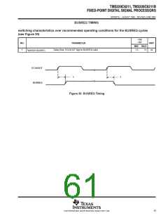
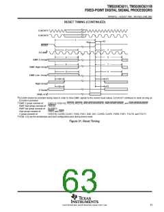
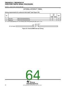
RESET TIMING
†
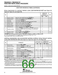
timing requirements for reset (see Figure 31)
−150
−167
NO.
UNIT
MIN
MAX
‡
Width of the RESET pulse (PLL stable)
10P
250
2P
ns
µs
ns
ns
1
t
w(RST)
§
Width of the RESET pulse (PLL needs to sync up)
¶
Setup time, HD boot configuration bits valid before RESET high
14
15
t
t
su(HD)
¶
Hold time, HD boot configuration bits valid after RESET high
2P
h(HD)
†
‡
§
P = 1/CPU clock frequency in ns. For example, when running parts at 167 MHz, use P = 6 ns.
This parameter applies to CLKMODE x1 when CLKIN is stable, and applies to CLKMODE x4 when CLKIN and PLL are stable.
This parameter applies to CLKMODE x4 only (it does not apply to CLKMODE x1). The RESET signal is not connected internally to the clock PLL
circuit. The PLL, however, may need up to 250 µs to stabilize following device power up or after PLL configuration has been changed. During
that time, RESET must be asserted to ensure proper device operation. See the clock PLL section for PLL lock times.
HD[4:3] are the boot configuration pins during device reset.
¶
†#||
switching characteristics over recommended operating conditions during reset
(see Figure 31)
−150
−167
NO.
PARAMETER
UNIT
MAX
MIN
2
3
t
t
t
t
t
t
t
t
t
t
t
t
Delay time, RESET low to ECLKIN synchronized internally
Delay time, RESET high to ECLKIN synchronized internally
Delay time, RESET low to EMIF Z group high impedance
Delay time, RESET high to EMIF Z group valid
Delay time, RESET low to EMIF high group invalid
Delay time, RESET high to EMIF high group valid
Delay time, RESET low to EMIF low group invalid
Delay time, RESET high to EMIF low group valid
Delay time, RESET low to high group invalid
2P + 3E
2P + 3E
2P + 3E
3P + 4E
3P + 4E
ns
ns
ns
ns
ns
ns
ns
ns
ns
ns
ns
ns
d(RSTL-ECKI)
d(RSTH-ECKI)
4
d(RSTL-EMIFZHZ)
d(RSTH-EMIFZV)
d(RSTL-EMIFHIV)
d(RSTH-EMIFHV)
d(RSTL-EMIFLIV)
d(RSTH-EMIFLV)
d(RSTL-HIGHIV)
d(RSTH-HIGHV)
d(RSTL-ZHZ)
5
3P + 4E
3P + 4E
3P + 4E
4P
6
2P + 3E
2P + 3E
2P
7
8
9
10
11
12
13
Delay time, RESET high to high group valid
Delay time, RESET low to Z group high impedance
Delay time, RESET high to Z group valid
2P
2P
d(RSTH-ZV)
†
#
||
P = 1/CPU clock frequency in ns. For example, when running parts at 167 MHz, use P = 6 ns.
E = ECLKIN period in ns
EMIF Z group consists of:
EA[21:2], ED[31:0], CE[3:0], BE[3:0], ARE/SDCAS/SSADS, AWE/SDWE/SSWE, and AOE/SDRAS/SSOE
EMIF high group consists of: HOLDA
EMIF low group consists of: BUSREQ
High group consists of:
Z group consists of:
HRDY and HINT
HD[15:0], CLKX0, CLKX1, FSX0, FSX1, DX0, DX1, CLKR0, CLKR1, FSR0, FSR1, TOUT0, and TOUT1.
62
POST OFFICE BOX 1443 • HOUSTON, TEXAS 77251−1443

 TI [ TEXAS INSTRUMENTS ]