ꢀ ꢁꢂ ꢃ ꢄ ꢅ ꢆꢇ ꢄ ꢈꢈ ꢉ ꢀ ꢁꢂ ꢃ ꢄꢅ ꢆꢇ ꢄꢈꢈꢊ
ꢋ ꢌꢍ ꢎꢏꢐꢑꢒ ꢌ ꢓꢀ ꢏꢌ ꢔꢌ ꢀꢕꢖ ꢂꢌ ꢔ ꢓꢕꢖ ꢑꢗ ꢒ ꢆꢎ ꢂ ꢂꢒ ꢗ ꢂ
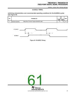
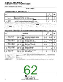
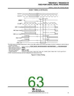
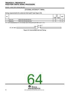
SPRS073L − AUGUST 1998 − REVISED JUNE 2004
HOST-PORT INTERFACE TIMING
†‡
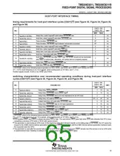
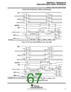
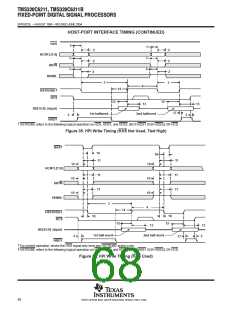
timing requirements for host-port interface cycles [C6211] (see Figure 33, Figure 34, Figure 35,
and Figure 36)
C6211−150
C6211−167
NO.
UNIT
MIN
5
MAX
§
1
2
t
t
t
t
t
t
t
t
Setup time, select signals valid before HSTROBE low
ns
ns
ns
ns
ns
ns
ns
ns
su(SELV-HSTBL)
h(HSTBL-SELV)
w(HSTBL)
§
Hold time, select signals valid after HSTROBE low
4
3
Pulse duration, HSTROBE low
4P
4P
5
4
Pulse duration, HSTROBE high between consecutive accesses
w(HSTBH)
§
Setup time, select signals valid before HAS low
10
11
12
13
su(SELV-HASL)
h(HASL-SELV)
su(HDV-HSTBH)
h(HSTBH-HDV)
§
Hold time, select signals valid after HAS low
3
Setup time, host data valid before HSTROBE high
Hold time, host data valid after HSTROBE high
5
3
Hold time, HSTROBE low after HRDY low. HSTROBE should not be inactivated
until HRDY is active (low); otherwise, HPI writes will not complete properly.
14
t
2
ns
h(HRDYL-HSTBL)
18
19
t
t
Setup time, HAS low before HSTROBE low
Hold time, HAS low after HSTROBE low
2
2
ns
ns
su(HASL-HSTBL)
h(HSTBL-HASL)
†
‡
§
HSTROBE refers to the following logical operation on HCS, HDS1, and HDS2: [NOT(HDS1 XOR HDS2)] OR HCS.
P = 1/CPU clock frequency in ns. For example, when running parts at 167 MHz, use P = 6 ns.
Select signals include: HCNTL[1:0], HR/W, and HHWIL.
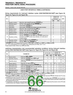
switching characteristics over recommended operating conditions during host-port interface
†‡
cycles [C6211] (see Figure 33, Figure 34, Figure 35, and Figure 36)
C6211−150
C6211−167
NO.
PARAMETER
UNIT
MIN MAX
¶
5
6
t
t
t
t
t
t
t
t
t
Delay time, HCS to HRDY
1
15
15
ns
ns
ns
ns
ns
ns
ns
ns
ns
d(HCS-HRDY)
#
Delay time, HSTROBE low to HRDY high
3
d(HSTBL-HRDYH)
d(HSTBL-HDLZ)
d(HDV-HRDYL)
oh(HSTBH-HDV)
d(HSTBH-HDHZ)
d(HSTBL-HDV)
d(HSTBH-HRDYH)
d(HASL-HRDYH)
7
Delay time, HSTROBE low to HD low impedance for an HPI read
Delay time, HD valid to HRDY low
2
8
2P − 4
2P
15
15
15
15
15
9
Output hold time, HD valid after HSTROBE high
Delay time, HSTROBE high to HD high impedance
Delay time, HSTROBE low to HD valid
3
3
3
3
3
15
16
17
20
||
Delay time, HSTROBE high to HRDY high
Delay time, HAS low to HRDY high
†
‡
¶
HSTROBE refers to the following logical operation on HCS, HDS1, and HDS2: [NOT(HDS1 XOR HDS2)] OR HCS.
P = 1/CPU clock frequency in ns. For example, when running parts at 167 MHz, use P = 6 ns.
HCS enables HRDY, and HRDY is always low when HCS is high. The case where HRDY goes high when HCS falls indicates that HPI is busy
completing a previous HPID write or READ with autoincrement.
#
||
This parameter is used during an HPID read. At the beginning of the first half-word transfer on the falling edge of HSTROBE, the HPI sends the
request to the EDMA internal address generation hardware, and HRDY remains high until the EDMA internal address generation hardware loads
the requested data into HPID.
This parameter is used after the second half-word of an HPID write or autoincrement read. HRDY remains low if the access is not an HPID write
or autoincrement read. Reading or writing to HPIC or HPIA does not affect the HRDY signal.
65
POST OFFICE BOX 1443 • HOUSTON, TEXAS 77251−1443

 TI [ TEXAS INSTRUMENTS ]