ꢀ ꢁ ꢂ ꢃ ꢄꢅ ꢆ ꢇ ꢄꢈꢈ ꢉ ꢀꢁ ꢂꢃ ꢄ ꢅ ꢆꢇ ꢄ ꢈꢈ ꢊ
ꢋ ꢌ ꢍꢎꢏ ꢐꢑ ꢒꢌ ꢓ ꢀ ꢏ ꢌ ꢔꢌ ꢀꢕꢖ ꢂ ꢌ ꢔꢓ ꢕꢖ ꢑ ꢗꢒ ꢆꢎꢂ ꢂꢒ ꢗꢂ
SPRS073L − AUGUST 1998 − REVISED JUNE 2005
HOLD/HOLDA TIMING
†
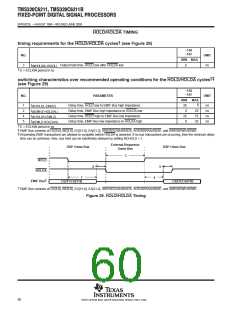
timing requirements for the HOLD/HOLDA cycles (see Figure 29)
−150
−167
NO.
UNIT
MIN MAX
3
t
Output hold time, HOLD low after HOLDA low
E
ns
oh(HOLDAL-HOLDL)
E = ECLKIN period in ns
†
†‡
switching characteristics over recommended operating conditions for the HOLD/HOLDA cycles
(see Figure 29)
−150
−167
NO.
PARAMETER
UNIT
MIN
2E
0
MAX
§
1
2
4
5
t
t
t
t
Delay time, HOLD low to EMIF Bus high impedance
Delay time, EMIF Bus high impedance to HOLDA low
Delay time, HOLD high to EMIF Bus low impedance
Delay time, EMIF Bus low impedance to HOLDA high
ns
ns
ns
ns
d(HOLDL-EMHZ)
d(EMHZ-HOLDAL)
d(HOLDH-EMLZ)
d(EMLZ-HOLDAH)
2E
7E
2E
2E
0
†
‡
§
E = ECLKIN period in ns
EMIF Bus consists of CE[3:0], BE[3:0], ED[31:0], EA[21:2], ARE/SDCAS/SSADS, AOE/SDRAS/SSOE, and AWE/SDWE/SSWE.
All pending EMIF transactions are allowed to complete before HOLDA is asserted. If no bus transactions are occurring, then the minimum delay
time can be achieved. Also, bus hold can be indefinitely delayed by setting NOHOLD = 1.
External Requestor
DSP Owns Bus
DSP Owns Bus
Owns Bus
3
HOLD
2
5
HOLDA
1
C6211/C6211B
4
†
EMIF Bus
C6211/C6211B
†
EMIF Bus consists of CE[3:0], BE[3:0], ED[31:0], EA[21:2], ARE/SDCAS/SSADS, AOE/SDRAS/SSOE, and AWE/SDWE/SSWE.
Figure 29. HOLD/HOLDA Timing
60
POST OFFICE BOX 1443 • HOUSTON, TEXAS 77251−1443

 TI [ TEXAS INSTRUMENTS ]