ꢀ ꢁꢂ ꢃ ꢄ ꢅ ꢆꢇ ꢄ ꢈꢈ ꢉ ꢀ ꢁꢂ ꢃ ꢄꢅ ꢆꢇ ꢄꢈꢈꢊ
ꢋ ꢌꢍ ꢎꢏꢐꢑꢒ ꢌ ꢓꢀ ꢏꢌ ꢔꢌ ꢀꢕꢖ ꢂꢌ ꢔ ꢓꢕꢖ ꢑꢗ ꢒ ꢆꢎ ꢂ ꢂꢒ ꢗ ꢂ
SPRS073L − AUGUST 1998 − REVISED JUNE 2005
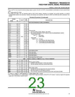
interrupt sources and interrupt selector
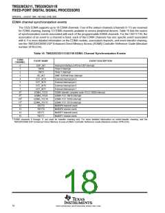
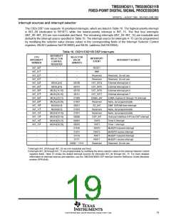
The C62x DSP core supports 16 prioritized interrupts, which are listed in Table 16. The highest-priority interrupt
is INT_00 (dedicated to RESET) while the lowest-priority interrupt is INT_15. The first four interrupts
(INT_00−INT_03) are non-maskable and fixed. The remaining interrupts (INT_04−INT_15) are maskable and
default to the interrupt source specified in Table 16. The interrupt source for interrupts 4−15 can be programmed
by modifying the selector value (binary value) in the corresponding fields of the Interrupt Selector Control
registers: MUXH (address 0x019C0000) and MUXL (address 0x019C0004).
Table 16. C6211/C6211B DSP Interrupts
INTERRUPT
CPU
INTERRUPT
NUMBER
SELECTOR
VALUE
(BINARY)
INTERRUPT
EVENT
SELECTOR
CONTROL
REGISTER
INTERRUPT SOURCE
†
†
†
†
‡
‡
‡
‡
‡
‡
‡
INT_00
INT_01
INT_02
INT_03
INT_04
INT_05
INT_06
INT_07
INT_08
INT_09
INT_10
−
−
−
RESET
NMI
−
−
−
Reserved
Reserved
EXT_INT4
EXT_INT5
EXT_INT6
EXT_INT7
EDMA_INT
Reserved
SD_INT
Reserved
Reserved
DSP_INT
TINT0
Reserved. Do not use.
−
−
Reserved. Do not use.
MUXL[4:0]
MUXL[9:5]
MUXL[14:10]
MUXL[20:16]
MUXL[25:21]
MUXL[30:26]
MUXH[4:0]
MUXH[9:5]
MUXH[14:10]
MUXH[20:16]
MUXH[25:21]
MUXH[30:26]
−
00100
00101
00110
00111
01000
01001
00011
01010
01011
00000
00001
00010
01100
01101
01110
01111
10000 − 11111
External interrupt pin 4
External interrupt pin 5
External interrupt pin 6
External interrupt pin 7
EDMA channel (0 through 15) interrupt
None, but programmable
EMIF SDRAM timer interrupt
None, but programmable
None, but programmable
Host-port interface (HPI)-to-DSP interrupt
Timer 0 interrupt
‡
INT_11
‡
‡
‡
‡
INT_12
INT_13
INT_14
INT_15
TINT1
Timer 1 interrupt
−
−
−
−
−
XINT0
McBSP0 transmit interrupt
McBSP0 receive interrupt
McBSP1 transmit interrupt
McBSP1 receive interrupt
Reserved. Do not use.
−
RINT0
−
XINT1
−
RINT1
−
Reserved
†
‡
Interrupts INT_00 through INT_03 are non-maskable and fixed.
Interrupts INT_04 through INT_15 are programmable by modifying the binary selector values in the Interrupt Selector Control
registers fields. Table 16 shows the default interrupt sources for Interrupts INT_04 through INT_15. For more detailed
information on interrupt sources and selection, see the TMS320C6000 DSP Interrupt Selector Reference Guide (literature
number SPRU646).
19
POST OFFICE BOX 1443 • HOUSTON, TEXAS 77251−1443

 TI [ TEXAS INSTRUMENTS ]