TMS320DM6437
Digital Media Processor
www.ti.com
SPRS345B–NOVEMBER 2006–REVISED MARCH 2007
Power Supplies Stable
MXI
CLKOUT0
POR
1
RESET
2
RESETOUT
3
SYSCLKREFCLK
(PLLC1)
PLL1 Clock
Div1 Clock
Div3 Clock
Div6 Clock
SYSCLK1
SYSCLK2
SYSCLK3
5
6
8
4
Boot and
Configuration Pins
Driven or Hi-Z
8
Config
Driven or Hi-Z
Z+/Low Group
(Z longer-to-low)
8
Z+/High Group
(Z longer-to-high)
9
Z+/Invalid Group
(Z longer-to-invalid)
Invalid
Z Group
Driven or Hi-Z
6
7
7
Z/Low Group
(Z-to-low)
Driven or Hi-Z
6
Z/High Group
(Z-to-high)
Driven or Hi-Z
6
DDR2 Z Group
DDR2 Low Group
DDR2 High Group
6
6
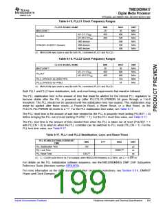
A. Pin reset behavior depends on which peripheral defaults to controlling the multiplexed pin. For more details on what
pin group (e.g., Z Group, Z/Low Group, Z/High Group, etc.) each pin belongs to, see Section 6.5.8, Pin Behaviors at
Reset.
Figure 6-8. Warm Reset (RESET) Timing(A)
Submit Documentation Feedback
Peripheral Information and Electrical Specifications
195

 TI [ TEXAS INSTRUMENTS ]