TMS320DM6437
Digital Media Processor
www.ti.com
SPRS345B–NOVEMBER 2006–REVISED MARCH 2007
6.6 External Clock Input From MXI/CLKIN Pin
The DM6437 device includes two options to provide an external clock input:
•
•
Use an on-chip oscillator with external crystal.
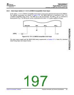
Use an external 1.8-V LVCMOS-compatible clock input.
The optimal external clock input frequency is 27 MHz. Section 6.6.1 provides more details on Option 1,
using an on-chip oscillator with external crystal. Section 6.6.2 provides details on Option 2, using an
external 1.8-V LVCMOS-compatible clock input.
6.6.1 Clock Input Option 1—Crystal
In this option, a crystal is used as the external clock input to the DM6437.
The 27-MHz oscillator provides the reference clock for all DM6437 subsystems and peripherals. The
on-chip oscillator requires an external 27-MHz crystal connected across the MXI and MXO pins, along
with two load capacitors, as shown in Figure 6-9. The external crystal load capacitors must be connected
only to the 27-MHz oscillator ground pin (MXVSS). Do not connect to board ground (VSS). The MXVDD pin
can be connected to the same 1.8 V power supply as DVDDR2
.
MXI/CLKIN
MXO
MXVSS
MXVDD
Crystal
27 MHz
C1
C2
1.8 V
Figure 6-9. 27-MHz System Oscillator
The load capacitors, C1 and C2, should be chosen such that the equation is satisfied (typical values are
C1 = C2 = 10 pF). CL in the equation is the load specified by the crystal manufacturer. All discrete
components used to implement the oscillator circuit should be placed as close as possible to the
associated oscillator pins (MXI and MXO) and to the MXVSS pin.
C1C2
CL +
(C1 ) C2)
Table 6-13. Input Requirements for Crystal
PARAMETER
MIN
TYP
MAX
UNIT
Start-up time (from power up until oscillating at stable frequency of 27
MHz)
4
ms
Oscillaton frequency
ESR
27
MHz
Ω
60
(1)Frequency stability
±50 or ±200
ppm
(1) For video and audio applications, stability of the input clock is very important. The user should select crystals with low enough ppm to
ensure good video and audio quality for the specific application. If the VPBE is used, TI recommends a 27-MHz, 50-ppm crystal to
ensure NTSC and PAL compliant output video. For more details on this NTSC and PAL compliant output video, see Section 6.10.2,
Video Processing Back-End (VPBE).
196
Peripheral Information and Electrical Specifications
Submit Documentation Feedback

 TI [ TEXAS INSTRUMENTS ]