TMS320DM6437
Digital Media Processor
www.ti.com
SPRS345B–NOVEMBER 2006–REVISED MARCH 2007
The EDMA supports two addressing modes: constant addressing and increment addressing. On the
DM6437, constant addressing mode is not supported by any peripheral or internal memory. For more
information on these two addressing modes, see the TMS320DM643x DMP Enhanced Direct Memory
Access (EDMA3) Controller User’s Guide (literature number SPRU987).
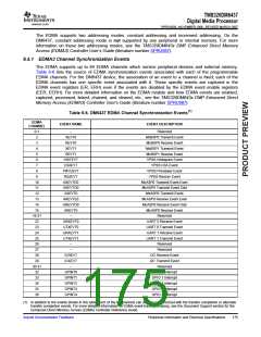
6.4.1 EDMA3 Channel Synchronization Events
The EDMA supports up to 64 EDMA channels which service peripheral devices and external memory.
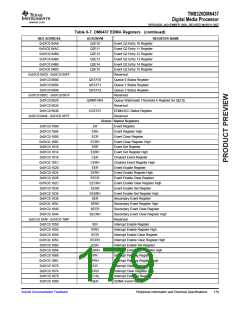
Table 6-6 lists the source of EDMA synchronization events associated with each of the programmable
EDMA channels. For the DM6437 device, the association of an event to a channel is fixed; each of the
EDMA channels has one specific event associated with it. These specific events are captured in the
EDMA event registers (ER, ERH) even if the events are disabled by the EDMA event enable registers
(EER, EERH). For more detailed information on the EDMA module and how EDMA events are enabled,
captured, processed, linked, chained, and cleared, etc., see the TMS320DM643x DMP Enhanced Direct
Memory Access (EDMA3) Controller User’s Guide (literature number SPRU987).
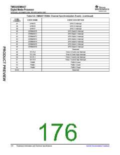
Table 6-6. DM6437 EDMA Channel Synchronization Events(1)
EDMA
CHANNEL
EVENT NAME
EVENT DESCRIPTION
0-1
2
–
Reserved
McBSP0 Transmit Event
McBSP0 Receive Event
McBSP1 Transmit Event
McBSP1 Receive Event
VPSS Histogram Event
VPSS H3A Event
XEVT0
REVT0
XEVT1
REVT1
HISTEVT
H3AEVT
PRVUEVT
RSZEVT
AXEVTE0
AXEVTO0
AXEVT0
AREVTE0
AREVTO0
AREVT0
–
3
4
5
6
7
8
VPSS Previewer Event
VPSS Resizer Event
McASP0 Transmit Event Even
McASP0 Transmit Event Odd
McASP0 Transmit Event
McASP0 Receive Event Even
McASP0 Receive Event Odd
McASP0 Receive Event
Reserved
9
10
11
12
13
14
15
16-21
22
23
24
25
26
27
28
29
30-31
32
33
34
35
36
URXEVT0
UTXEVT0
URXEVT1
UTXEVT1
–
UART 0 Receive Event
UART 0 Transmit Event
UART 1 Receive Event
UART 1 Transmit Event
Reserved
–
Reserved
ICREVT
ICXEVT
–
I2C Receive Event
I2C Transmit Event
Reserved
GPINT0
GPINT1
GPINT2
GPINT3
GPINT4
GPIO 0 Interrupt
GPIO 1 Interrupt
GPIO 2 Interrupt
GPIO 3 Interrupt
GPIO 4 Interrupt
(1) In addition to the events shown in this table, each of the 64 channels can also be synchronized with the transfer completion or alternate
transfer completion events. For more detailed information on EDMA event-transfer chaining, see the Document Support section for the
Enhanced Direct Memory Access (EDMA) Controller Reference Guide.
Submit Documentation Feedback
Peripheral Information and Electrical Specifications
175

 TI [ TEXAS INSTRUMENTS ]