TMS320DM6437
Digital Media Processor
www.ti.com
SPRS345B–NOVEMBER 2006–REVISED MARCH 2007
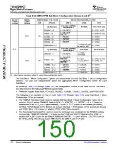
3.7.3.13.5 EMIFA/VPSS Sub-Block 2 Configuration Choices
The 3 pins in the EMIFA/VPSS Sub-Block 2 are standalone (non-multiplexed) pins. They always function
as EMIFA control pins EM_WAIT/(RDY/BSY), EM_OE, and EM_WE. No pin mux selection is necessary
for this Sub-Block.
3.7.3.13.6 EMIFA/VPSS Sub-Block 3 Configuration Choices
The 8 pins in the EMIFA/VPSS Sub-Block 3 are multiplexed between:
•
•
•
EMIFA Address Pins EM_A[12:5]
PCI pins: PCBE3, PIDSEL, AD[24:19]
GPIO pins GP[96:89]
The pin functions in the EMIFA/VPSS Sub-Block 3 are determined by the following PINMUX register
fields:
•
•
PINMUX1.PCIEN
PINMUX0.AEM
Once the Major Configuration Option for the EMIFA/VPSS Block (see Section 3.7.3.13.2, EMIFA/VPSS
Block Major Configuration Choices) is chosen, no further actions are necessary to refine the EMIFA/VPSS
Sub-Block 3 pin selection. For instructions on configuring the EMIFA/VPSS Block, see Section 3.7.3.13.1,
EMIFA/VPSS Block Pin Selection Procedure.
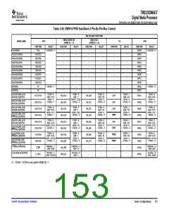
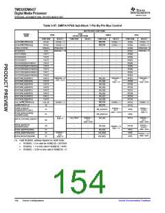
Table 3-55 summarizes the pin selections in the EMIFA/VPSS Sub-Block 3 based on the PINMUX
selections.
Table 3-55. EMIFA/VPSS Sub-Block 3 Configuration Choices
MAJOR
CONFIG
OPTION
PINMUX SELECTION FIELDS
RESULTING PERIPHERALS/PINS
EMIFA
PCIEN
AEM
PCI
GPIO
A
B
C
D
E
F
0
0
0
0
0
1
1
000
001
011
100
101
000
101
-
-
-
-
-
-
GP[96:89]
EM_A[12:5]
-
EM_A[12:5]
-
-
-
GP[96:89]
GP[96:89]
PCBE3, PIDSEL, AD[24:19]
PCBE3, PIDSEL, AD[24:19]
-
-
-
-
G
The following is an example on how to read Table 3-55 using Sub-Block 3 Major Configuration C as an
example:
•
The PINMUX Selection Fields columns indicate that Sub-Block 3 Major Configuration Option C is
selected through PINMUX1.PCIEN = 0 and PINMUX0.AEM = 3.
•
The Resulting Peripherals/Pins columns show the functional pins resulting from the PINMUX setting. In
Major Configuration C, the user gets EMIFA address pins EM_A[12:5] from Sub-Block 3.
Submit Documentation Feedback
Device Configurations
151

 TI [ TEXAS INSTRUMENTS ]