TMS320C6678
Multicore Fixed and Floating-Point Digital Signal Processor
SPRS691D—April 2013
www.ti.com
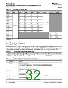
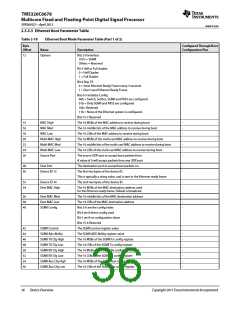
Table 2-10
BAR Config / PCIe Window Sizes
32-Bit Address Translation
64-Bit Address Translation
BAR cfg
0b0000
0b0001
0b0010
0b0011
0b0100
0b0101
0b0110
0b0111
0b1000
0b1001
0b1010
0b1011
BAR0
BAR1
32
16
16
32
16
16
32
32
64
4
BAR2
32
BAR3
32
BAR4
32
BAR5
BAR2/3
BAR4/5
16
32
64
32
32
64
32
32
64
16
64
64
32
64
64
Clone of BAR4
32
64
64
32
64
128
256
128
256
256
PCIe MMRs
64
128
128
128
256
128
128
128
4
4
0b1100
0b1101
0b1110
0b1111
256
256
512
512
1024
2048
1024
2048
End of Table 2-10
2.5.2.5 I2C Boot Device Configuration
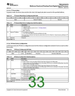
2.5.2.5.1 I2C Master Mode
In master mode, the I2C device configuration uses ten bits of device configuration instead of seven as used in other
boot modes. In this mode, the device will make the initial read of the I2C EEPROM while the PLL is in bypass mode.
The initial read will contain the desired clock multiplier, which will be set up prior to any subsequent reads.
Figure 2-7
I2C Master Mode Device Configuration Bit Fields
12
11
10
9
8
7
6
5
4
3
Reserved
Speed
Address
Mode
Parameter Index
Table 2-11
I2C Master Mode Device Configuration Field Descriptions
Bit
12
11
Field
Description
Reserved
Speed
Reserved
I2C data rate configuration
0 = I2C slow mode. Initial data rate is CORECLK/5000 until PLLs and clocks are programmed
1 = I2C fast mode. Initial data rate is CORECLK/250 until PLLs and clocks are programmed
10
Address
Mode
I2C bus address configuration
0 = Boot from I2C EEPROM at I2C bus address 0x50
1 = Boot from I2C EEPROM at I2C bus address 0x51
9-8
I2C operation mode
0 = Master mode
3 = Passive mode (see section 2.5.2.5.2 ‘‘I2C Passive Mode’’)
Others = Reserved
7-3
Parameter Index
Identifies the index of the configuration table initially read from the I2C EEPROM
This value can range from 0 to 31.
End of Table 2-11
32
Device Overview
Copyright 2013 Texas Instruments Incorporated

 TI [ TEXAS INSTRUMENTS ]