TMS320C6678
Multicore Fixed and Floating-Point Digital Signal Processor
SPRS691D—April 2013
www.ti.com
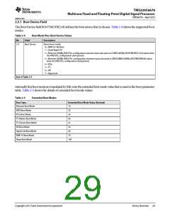
2.5.2 Device Configuration Field
The device configuration fields BOOTMODE[9:3] are used to configure the boot peripheral and, therefore, the bit
definitions depend on the boot mode
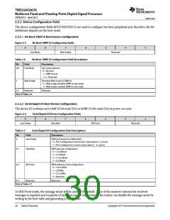
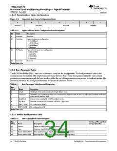
2.5.2.1 No Boot/ EMIF16 Boot Device Configuration
Figure 2-3
9
No Boot/ EMIF16 Configuration Fields
8
7
6
5
4
3
Sub-Mode
Wait Enable
Reserved
Table 2-6
No Boot / EMIF16 Configuration Field Descriptions
Description
Bit
Field
Sub-Mode
9-8
Sub mode selection.
0 = No boot
1 = EMIF16 boot
2 -3 = Reserved
7
Wait Enable
Reserved
Extended Wait mode for EMIF16.
0 = Wait enable disabled (EMIF16 sub mode)
1 = Wait enable enabled (EMIF16 sub mode)
6-3
Reserved
End of Table 2-6
2.5.2.2 Serial Rapid I/O Boot Device Configuration
The device ID is always set to 0xff (8-bit node IDs) or 0xffff (16 bit node IDs) at power-on reset.
Figure 2-4
Serial Rapid I/O Device Configuration Fields
9
8
7
6
5
4
3
Lane Setup
Data Rate
Ref Clock
Reserved
Table 2-7
Serial Rapid I/O Configuration Field Descriptions
Field Description
Bit
9
Lane Setup
SRIO port and lane configuration
0 = Port Configured as 4 ports each 1 lane wide (4 -1× ports)
1 = Port Configured as 2 ports 2 lanes wide (2 – 2× ports)
8-7
6-5
4-3
Data Rate
SRIO data rate configuration
0 = 1.25 GBaud
1 = 2.5 GBaud
2 = 3.125 GBaud
3 = 5.0 GBaud
Ref Clock
Reserved
SRIO reference clock configuration
0 = 156.25 MHz
1 = 250 MHz
2 = 312.5 MHz
3 = Reserved
Reserved
End of Table 2-7
In SRIO boot mode, the message mode will be enabled by default. If use of the memory reserved for received
messages is required and reception of messages cannot be prevented, the master can disable the message mode by
writing to the boot table and generating a boot restart.
30
Device Overview
Copyright 2013 Texas Instruments Incorporated

 TI [ TEXAS INSTRUMENTS ]