TMS320C6678
Multicore Fixed and Floating-Point Digital Signal Processor
SPRS691D—April 2013
www.ti.com
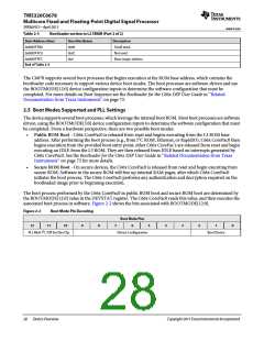
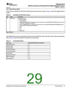
2.5.1 Boot Device Field
The Boot Device field BOOTMODE[2:0] defines the boot device that is chosen. Table 2-4 shows the supported boot
modes.
Table 2-4
Boot Mode Pins: Boot Device Values
Description
Bit
Field
Boot Device
2-0
Device boot mode
0 = EMIF16 / No Boot
1 = Serial Rapid I/O
2 = Ethernet (SGMII) (PASS PLL configuration assumes input rate same as CORECLK(P|N); BOOTMODE[12:10] values drive
the PASS PLL configuration during boot)
3 = Ethernet (SGMII) (PASS PLL configuration assumes input rate same as SRIOSGMIICLK(P|N); BOOTMODE[9:8] values
drive the PASS PLL configuration during boot)
4 = PCIe
5 = I2C
6 = SPI
7 = HyperLink
End of Table 2-4
Internally this boot mode are translated by RBL into the extended boot mode value that is used in the boot parameter
table. Table 2-5 shows the details of extended boot mode values.
Table 2-5
Boot Type
Extended Boot Modes
Extended Boot Mode Value (Decimal)
Ethernet Boot Mode
SRIO Boot Mode
10
20
30
40
41
50
60
70
100
PCIe Boot Mode
I2C Master Boot Mode
I2C Passive Boot Mode
SPI Boot Mode
HyperLink Boot Mode
EMIF 16 Boot Mode
Sleep Boot Mode
Copyright 2013 Texas Instruments Incorporated
Device Overview 29

 TI [ TEXAS INSTRUMENTS ]