TMS320C6672
Multicore Fixed and Floating-Point Digital Signal Processor
SPRS708C—February 2012
www.ti.com
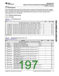
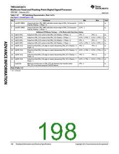
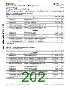
Table 7-67
SPI Switching Characteristics (Part 2 of 2)
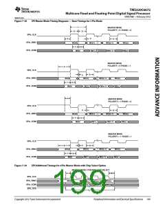
(See Figure 7-38 and Figure 7-39)
No.
Parameter
Min
0.5*tc - 2
Max
Unit
6
6
toh(SPC-SIMO)
toh(SPC-SIMO)
Output hold time, SPIx_SIMO valid after receive edge of SPIx_CLK except for
final bit. Polarity = 1 Phase = 0
ns
Output hold time, SPIx_SIMO valid after receive edge of SPIx_CLK except for
final bit. Polarity = 1 Phase = 1
0.5*tc - 2
ns
Additional SPI Master Timings — 4 Pin Mode with Chip Select Option
19 td(SCS-SPC)
19 td(SCS-SPC)
19 td(SCS-SPC)
19 td(SCS-SPC)
20 td(SPC-SCS)
Delay from SPIx_SCS\ active to first SPIx_CLK. Polarity = 0 Phase = 0
Delay from SPIx_SCS\ active to first SPIx_CLK. Polarity = 0 Phase = 1
Delay from SPIx_SCS\ active to first SPIx_CLK. Polarity = 1 Phase = 0
Delay from SPIx_SCS\ active to first SPIx_CLK. Polarity = 1 Phase = 1
2*P2 - 5
2*P2 + 5
ns
0.5*tc + (2*P2) - 5 0.5*tc + (2*P2) + 5 ns
2*P2 - 5 2*P2 + 5 ns
0.5*tc + (2*P2) - 5 0.5*tc + (2*P2) + 5 ns
1*P2 - 5 1*P2 + 5 ns
Delay from final SPIx_CLK edge to master deasserting SPIx_SCS\. Polarity = 0
Phase = 0
20 td(SPC-SCS)
20 td(SPC-SCS)
20 td(SPC-SCS)
tw(SCSH)
Delay from final SPIx_CLK edge to master deasserting SPIx_SCS\. Polarity = 0
Phase = 1
0.5*tc + (1*P2) - 5 0.5*tc + (1*P2) + 5 ns
1*P2 - 5 1*P2 + 5 ns
0.5*tc + (1*P2) - 5 0.5*tc + (1*P2) + 5 ns
2*P2 - 5 ns
Delay from final SPIx_CLK edge to master deasserting SPIx_SCS\. Polarity = 1
Phase = 0
Delay from final SPIx_CLK edge to master deasserting SPIx_SCS\. Polarity = 1
Phase = 1
Minimum inactive time on SPIx_SCS\ pin between two transfers when
SPIx_SCS\ is not held using the CSHOLD feature.
End of Table 7-67
1 P2 = 1/SYSCLK7
198
Peripheral Information and Electrical Specifications
Copyright 2012 Texas Instruments Incorporated

 TI [ TEXAS INSTRUMENTS ]