TMP435
www.ti.com
SBOS495A –MARCH 2010–REVISED APRIL 2010
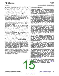
Consecutive Alert Register
does not trip on the measured temperature falling
edges. Allowable hysteresis values are shown in
Table 11. The default hysteresis value is 10°C,
whether the device is operating in the standard or
extended mode setting.
The value in the Consecutive Alert Register (address
22h) determines how many consecutive out-of-limit
measurements must occur on
a measurement
channel before the ALERT/THERM2 or the THERM
signal is activated. The value in this register does not
affect bits in the Status Register. Values of one, two,
three, or four consecutive conversions can be
selected; one conversion is the default. This function
allows additional filtering for the ALERT/THERM2 or
the THERM pin. Table 13 shows the consecutive
alert bits. For bit descriptions, refer to Table 10.
Identification Registers
The TMP435 allows for the two-wire bus controller to
query the device for manufacturer and device IDs to
enable the device for software identification of the
device at the particular two-wire bus address. The
manufacturer ID is obtained by reading from pointer
address FEh. The TMP435 returns 55h for the
manufacturer code. The device ID is obtained by
reading from pointer address FDh. The TMP435
returns 31h for the device ID (see Table 3). These
registers are read-only.
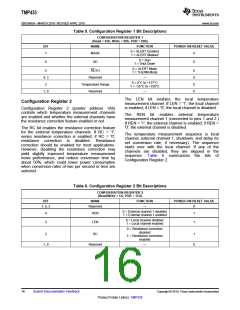
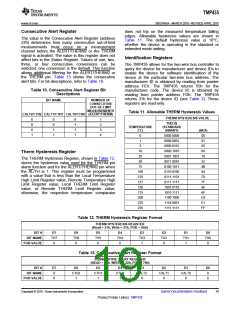
Table 10. Consecutive Alert Register Bit
Descriptions
BIT NAME
NUMBER OF
CONSECUTIVE
OUT-OF-LIMIT
MEASUREMENTS
Table 11. Allowable THERM Hysteresis Values
CALT2/CTH2 CALT1/CTH1 CALT0/CTH0 (ALERT/THERM)
THERM HYSTERESIS VALUE
0
0
0
1
0
0
1
1
0
1
1
1
1
2
3
4
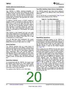
TH[7:0]
TEMPERATURE
(°C)
(STANDARD
BINARY)
(HEX)
00
0
0000 0000
0000 0001
0000 0101
0000 1010
0001 1001
0011 0010
0100 1011
0110 0100
0111 1101
0111 1111
1001 0110
1010 1111
1100 1000
1110 0001
1111 1111
1
01
space.
5
05
10
0A
19
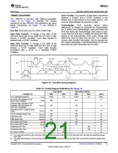
Therm Hysteresis Register
25
The THERM Hysteresis Register, shown in Table 12,
stores the hysteresis value used for the THERM pin
alarm function and for the ALERT/THERM2 pin when
the AL/TH is 1. This register must be programmed
with a value that is less than the Local Temperature
High Limit Register value, Remote Temperature High
Limit Register value, Local THERM Limit Register
value, or Remote THERM Limit Register value;
otherwise, the respective temperature comparator
50
32
75
4B
64
100
125
127
150
175
200
225
255
7D
7F
96
AF
C8
E1
FF
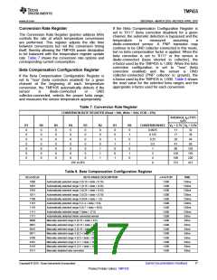
Table 12. THERM Hysteresis Register Format
THERM HYSTERESIS REGISTER
(Read = 21h, Write = 21h, POR = 0Ah)
BIT #
BIT NAME
D7
TH7
0
D6
TH6
0
D5
TH5
0
D4
TH4
0
D3
TH3
1
D2
TH2
0
D1
TH1
1
D0
TH0
0
POR VALUE
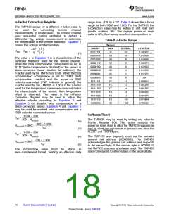
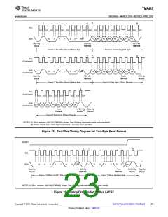
Table 13. Consecutive Alert Register Format
CONSECUTIVE ALERT REGISTER
(READ = 22h, WRITE = 22h, POR = 70h)
BIT #
BIT NAME
D7
0
D6
CTH2
1
D5
CTH1
1
D4
CTH0
1
D3
CALT2
0
D2
CALT1
0
D1
CALT0
0
D0
0
POR VALUE
0
0
Copyright © 2010, Texas Instruments Incorporated
Submit Documentation Feedback
19
Product Folder Link(s): TMP435

 TI [ TEXAS INSTRUMENTS ]