TMP435
SBOS495A –MARCH 2010–REVISED APRIL 2010
www.ti.com
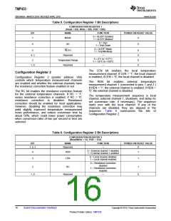
Table 5. Configuration Register 1 Bit Descriptions
CONFIGURATION REGISTER 1
(Read = 03h, Write = 09h, POR = 00h)
BIT
NAME
FUNCTION
POWER-ON RESET VALUE
0 = ALERT Enabled
1 = ALERT Masked
7
MASK
0
0
0 = Run
1 = Shut Down
6
SD
0 = ALERT Mode
1 = THERM Mode
5
AL/TH
Reserved
0
0
0
0
4, 3
2
—
0 = 0°C to +127°C
1 = −55°C to +150°C
Temperature Range
Reserved
1, 0
—
The LEN bit enables the local temperature
measurement channel. If LEN = '1', the local channel
is enabled; if LEN = '0', the local channel is disabled.
Configuration Register 2
Configuration Register
2
(pointer address 1Ah)
controls which temperature measurement channels
are enabled and whether the external channels have
the resistance correction feature enabled or not.
The REN bit enables external temperature
measurement channel 1 (connected to pins 1 and 2.)
If REN = '1', the external channel is enabled; if REN =
'0', the external channel is disabled.
The RC bit enables the resistance correction feature
for the external temperature channels. If RC = '1',
series resistance correction is enabled; if RC = '0',
resistance correction is disabled. Resistance
correction should be enabled for most applications.
However, disabling the resistance correction may
yield slightly improved temperature measurement
noise performance, and reduce conversion time by
about 50%, which could lower power consumption
when conversion rates of two per second or less are
selected.
The temperature measurement sequence is local
channel, external channel 1, shutdown, and delay (to
set conversion rate, if necessary). The sequence
starts over with the local channel. If any of the
channels are disabled, they are skipped in the
sequence. Table
6
summarizes the bits of
Configuration Register 2.
space
Table 6. Configuration Register 2 Bit Descriptions
CONFIGURATION REGISTER 2
(Read/Write = 1A, POR = 1Ch)
BIT
NAME
FUNCTION
POWER-ON RESET VALUE
7, 6, 5
Reserved
—
0
0 = External channel 1 disabled
1 = External channel 1 enabled
4
3
REN
LEN
1
1
0 = Local channel disabled
1 = Local channel enabled
0 = Resistance correction
disabled
1 = Resistance correction
enabled
2
RC
1
0
1, 0
Reserved
—
16
Submit Documentation Feedback
Copyright © 2010, Texas Instruments Incorporated
Product Folder Link(s): TMP435

 TI [ TEXAS INSTRUMENTS ]