TMDS361
www.ti.com ............................................................................................................................................................................................ SLLS919–DECEMBER 2008
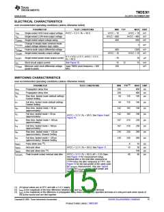
SWITCHING CHARACTERISTICS
over recommended operating conditions (unless otherwise noted)
PARAMETER
TEST CONDITIONS
HPD_SINK to HPD[1:3]
MIN TYP
MAX
20
UNIT
ns
tPD1(HPD)
tS1(HPD)
tS2(HPD)
tZ(HPD)
HPD_SINK propagation delay
Selecting port HPD switch time
Deselecting port HPD switch time
Low-power to high-level propagation delay
12
17
14
13
S[1:2] to HPD[1:3]
S[1:2] to HPD[1:3]
LP to HPD[1:3]
30
ns
22
ns
20
ns
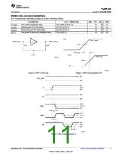
5 V
HPD_SINK
HPD
BUFFER
HPD Input
HPD Output
5 pF
2.5 V
5 pF
0 V
tPD1(HPD)
3.3 V
HPD[1:3]
S0367-01
1.65 V
0 V
T0387-01
Figure 1. HPD Test Circuit
Figure 2. HPD Timing Diagram #1
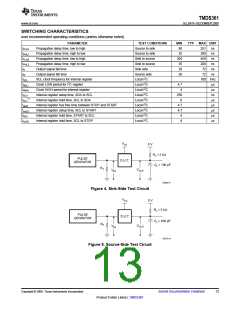
5 V
HPD_SINK
0 V
5 V
S1
S2
2.5 V
0 V
5 V
0 V
VCC
VCC/2
0 V
HPD2
HPD1
LP
ts2
VCC
VCC/2
0 V
ts1
5 V
2.5 V
0 V
tz
T0423-01
Figure 3. HPD Timing Diagram #2
Copyright © 2008, Texas Instruments Incorporated
Submit Documentation Feedback
11
Product Folder Link(s) :TMDS361

 TI [ TEXAS INSTRUMENTS ]