TLVM13640
SLVSGJ7 – APRIL 2022
www.ti.com
9.2.2.2 Detailed Design Procedure
9.2.2.2.1 Output Voltage Setpoint
For an output voltage of –5 V, choose upper and lower feedback resistance of 102 kΩ and 25.5 kΩ, respectively,
using Equation 1.
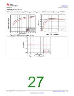
9.2.2.2.2 IBB Maximum Output Current
The achievable output current with an IBB topology using the TLVM13640 is IOUT(max) = ILDC(max) × (1 – D),
where ILDC(max) = 4 A is the rated current of the module and D = |VOUT| / (VIN + |VOUT|) is the IBB duty cycle.
Figure 9-11 provides the maximum output current capability as a function of input voltage for output voltage
setpoints of –3.3 V and –5 V.
9.2.2.2.3 Switching Frequency Selection
Connect a 10.7-kΩ resistor from RT to AGND to set a switching frequency of 1.2 MHz, which is ideal for an
output of –5 V as it establishes an inductor peak-to-peak ripple current of approximately 40% of the 4-A rated
module current at the nominal input voltage of 12 V.
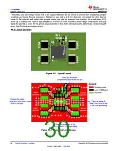
9.2.2.2.4 Input Capacitor Selection
Use two 10-µF, 50-V, X7R-dielectric ceramic capacitors in 1210 case size connected symmetrically from the
VIN1 and VIN2 pins to PGND as close as possible to the module. More specifically, these capacitors appear
from the drain of the internal high-side MOSFET to the source of the low-side MOSFET, effectively connecting
from the positive input voltage to the negative output voltage terminals.
The sum of the input and output voltages, VIN + |–VOUT|, is the effective applied voltage across the capacitors.
The total effective capacitance at 25°C and input voltages of 12 V and 24 V (corresponding to applied voltages
of 17 V and 29 V) is approximately 15 µF and 10 µF, respectively. Check the capacitance versus voltage
derating curve in the capacitor data sheet.
Use an additional 10-µF, 50-V capacitor directly across the input. This capacitor is designated as CIN3 and
connects across the VIN+ and VIN– terminals as shown in Figure 9-10.
9.2.2.2.5 Output Capacitor Selection
For this IBB design example, use two 47-µF, 10-V, X7R-dielectric ceramic capacitors in 1210 case size
connected symmetrically close to the module from the VOUT1 and VOUT2 pins to PGND. The total effective
capacitance is approximately 52 µF with DC bias of 5 V.
9.2.2.2.6 Other Considerations
Short RBOOT to CBOOT and connect VLDOIN to the power stage GND terminal (corresponding to VOUT1,
VOUT2 of the module) for best efficiency.
The right-half-plane zero of an IBB topology is at its lowest freqeuncy at minimum input voltage and highest load
current. Using the TLVM13640 quickstart calculator, select the output capacitance to set that the loop crossover
freqeuncy at less than one third of the lowest right-half-plane zero frequency for a given application.
Copyright © 2022 Texas Instruments Incorporated
26
Submit Document Feedback
Product Folder Links: TLVM13640

 TI [ TEXAS INSTRUMENTS ]