TLK10002
SLLSE75 –MAY 2011
www.ti.com
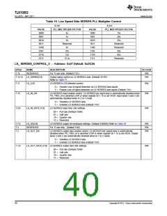
Table 16. Low Speed Side SERDES PLL Multiplier Control
6.3:0
6.3:0
VALUE
0000
0001
0010
0011
0100
0101
0110
0111
PLL MULTIPLIER FACTOR
VALUE
1000
1001
1010
1011
1100
1101
1110
1111
PLL MULTIPLIER FACTOR
4x
5x
15x
20x
6x
25x
Reserved
8x
Reserved
Reserved
50x
10x
12x
65x
12.5x
Reserved
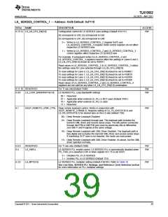
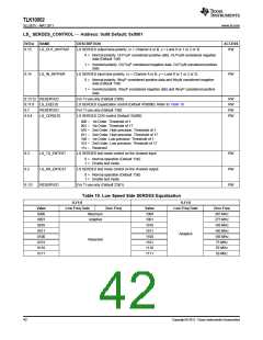
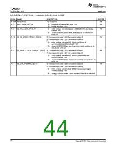
LS_ SERDES_CONTROL_2 — Address: 0x07 Default: 0xDC04
BIT(s)
7.15
NAME
DESCRIPTION
ACCESS
RW
RESERVED
LS_SWING[2:0]
For TI use only. (Default 1’b1)
7.14:12
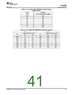
Output swing control on LS SERDES side. (Default 3’b101)
RW
Refer to Table 17.
7.11
7.10
LS_LOS
LS SERDES LOS detector control
RW
RW
0 = Disable Loss of signal detection on LS SERDES lane inputs
1 = Enable Loss of signal detection on LS SERDES lane inputs (Default 1’b1)
LS_IN_EN
LS SERDES input enable control. LS SERDES per input lane is automatically disabled when
PD_TRXx_N is asserted LOW or when register bit 1.15 is set HIGH. Input lanes 3 and 2 are
automatically disabled when in 2 to 1 mode
0 = Disables LS SERDES lane
1 = Enables LS SERDES lane (Default 1’b1)
7.9:8
LS_IN_RATE [1:0]
LS SERDES input lane rate settings
RW
00 = Full rate (Default 2’b00)
01 = Half rate
10 = Quarter rate
11 = Reserved
7.7:4
7.3
LS_DE[3:0]
RESERVED
LS_OUT_EN
LS SERDES output de-emphasis settings. (Default 4’b0000) Refer to Table 18
For TI use only . (Default 1’b0)
RW
RW
RW
7.2
LS SERDES output lane enable control. LS SERDES per output lane is automatically
disabled when PD_TRXx_N is asserted LOW or when register bit 1.15 is set HIGH. Output
lanes 3 and 2 are automatically disabled when in 1 to 2 mode.
0 = Disables LS SERDES lane
1 = Enables LS SERDES lane (Default 1’b1)
7.1:0
LS_OUT_RATE [1:0] LS SERDES output lane rate settings
RW
00 = Full rate (Default 2’b00)
01 = Half rate
10 = Quarter rate
11 = Reserved
40
Copyright © 2011, Texas Instruments Incorporated

 TI [ TEXAS INSTRUMENTS ]