TLK10002
www.ti.com
SLLSE75 –MAY 2011
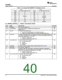
LS_ SERDES_CONTROL_1 — Address: 0x06 Default: 0xF115
BIT(s)
NAME
DESCRIPTION
ACCESS
6.15:12 LS_LN_CFG_EN[3:0]
Configuration control for LS SERDES Lane settings (Default 4’b1111)
[3] corresponds to LN3, [2] corresponds to LN2
[1] corresponds to LN1, [0] corresponds to LN0
0 = Writes to LS_SERDES_CONTROL_2 (register 0x07) and
RW
LS_SERDES_CONTROL_3 (register 0x08) control registers do not affect
respective LS SERDES lane
1 = Writes to LS_SERDES_CONTROL_2 and LS_SERDES_CONTROL_3
control registers affect respective LS SERDES lane
For example, if subsequent writes to LS_SERDES_CONTROL_2 and
LS_SERDES_CONTROL_3 registers need to affect the settings in Lanes 0 and 1,
LS_LN_CFG_EN[3:0] should be set to 4’b0011
Read values in LS_SERDES_CONTROL_2 & LS_SERDES_CONTROL_3 reflect
the settings value for Lane selected through LS_LN_CFG_EN[3:0].
To read settings for Lane 0, LS_LN_CFG_EN[3:0] should be set to 4’b0001
To read settings for Lane 1, LS_LN_CFG_EN[3:0] should be set to 4’b0010
To read settings for Lane 2, LS_LN_CFG_EN[3:0] should be set to 4’b0100
To read settings for Lane 3, LS_LN_CFG_EN[3:0] should be set to 4’b1000
Read values of LS_SERDES_CONTROL_2 and LS_SERDES_CONTROL_3
registers are not valid for any other LS_LN_CFG_EN[3:0] combination
6.11:10 RESERVED
For TI use only(Default 2’b00)
RW
RW
6.9:8
LS_LOOP_BANDWIDTH[1:0]
LS SERDES PLL Loop Bandwidth settings
00 = Reserved
01 = Applicable when external JC_PLL is NOT used (Default 2’b01)
10 = Applicable when external JC_PLL is used
11 = Reserved
6.7
DEEP_REMOTE_LPBK_CTRL Deep remote loopback control. Works in conjunction with
RW
DEEP_REMOTE_LPBK(B:3). Requires setting of LS_TX_ENTEST(8.3) and
LS_RX_ENTEST(8.2) for desired lane on the LS side (default 1'b0).
00= Deep Remote Loopback Disabled
01= Deep Remote Loopback through pad. The loopback path includes the
transmit CML driver and receive sense amps. The link partner connected
through INA*P/N or INB*P/N pins must be electrically idle at differential
zero with P and N signals at the same voltage.
10= Deep Remote Loopback with CML Driver Disabled. The loopback path is
fully digital and excludes the transmit CML driver and receive sense amps.
If monitoring OUT* pins is not required, this mode can save power.
11= Deep Remote Loopback with CML Driver Enabled. As above, but the CML
driver operates normally.
6.6:5
6.4
RESERVED
LS_ENPLL
For TI use only (Default 2’b00)
RW
RW
LS SERDES PLL enable control. LS SERDES PLL is automatically disabled when
PD_TRXx_N is asserted LOW or when register bit 1.15 is set HIGH.
0 = Disables PLL in LS SERDES
1 = Enables PLL in LS SERDES (Default 1’b1)
6.3:0
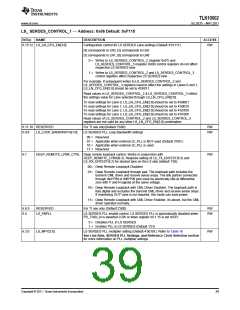
LS_MPY[3:0]
LS SERDES PLL multiplier setting (Default 4’b0101). Refer to Table 16
RW
See Line Rate, SERDES PLL Settings, and Reference Clock Selection section
for more information on PLL multiplier settings
Copyright © 2011, Texas Instruments Incorporated
39

 TI [ TEXAS INSTRUMENTS ]