TLK10002
www.ti.com
SLLSE75 –MAY 2011
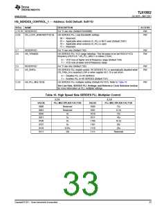
HS_SERDES_CONTROL_1 — Address: 0x02 Default: 0x811D
BIT(s)
NAME
DESCRIPTION
ACCESS
RW
2.15:10 RESERVED
For TI use only (Default 6'b100000)
HS SERDES PLL Loop Bandwidth settings
2.9:8
HS_LOOP_BANDWIDTH[1:0]
RW
00 = Reserved
01 = Applicable when external JC_PLL is NOT used (Default 2’b01)
10 = Applicable when external JC_PLL is used
11 = Reserved
2.7
2.6
RESERVED
For TI use only (Default 1’b0)
RW
RW
HS_VRANGE
HS SERDES PLL VCO range selection. This bit needs to be set HIGH if VCO
frequency (REFCLK * HS_PLL_MULT) is below 2.5GHz
0 = VCO runs at higher end of frequency range (Default 1’b0)
1 = VCO runs at lower end of frequency range
2.5
2.4
RESERVED
HS_ENPLL
For TI use only (Default 1’b0)
RW
HS SERDES PLL enable control. HS SERDES PLL is automatically disabled when
PD_TRXx_N is asserted LOW or when register bit 1.15 is set HIGH.
RW
0 = Disables PLL in HS SERDES
1 = Enables PLL in HS SERDES (Default 1’b1)
2.3:0
HS_PLL_MULT[3:0]
HS SERDES PLL multiplier setting (Default 4’b1101). Refer to Table 10
RW
See Line Rate, SERDES PLL Settings, and Reference Clock Selection section
for more information on PLL multiplier settings
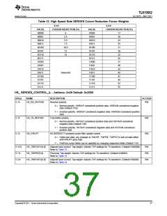
Table 10. High Speed Side SERDES PLL Multiplier Control
2.3:0
2.3:0
VALUE
0000
0001
0010
0011
0100
0101
0110
0111
PLL MULTIPLIER FACTOR
VALUE
1000
1001
1010
1011
1100
1101
1110
1111
PLL MULTIPLIER FACTOR
Reserved
Reserved
4x
12x
12.5x
15x
5x
16x
6x
16.5x
20x
8x
8.25x
10x
25x
Reserved
Copyright © 2011, Texas Instruments Incorporated
33

 TI [ TEXAS INSTRUMENTS ]