TLK10002
www.ti.com
SLLSE75 –MAY 2011
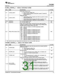
GLOBAL_CONTROL_1 — Address: 0x00 Default: 0x0600
BIT(s)
NAME
DESCRIPTION
ACCESS
Global reset (Channel A & B).
0 = Normal operation (Default 1’b0)
RW
SC(1)
0.15
GLOBAL_RESET
1 = Resets TX and RX datapath including MDIO registers. Equivalent to
asserting RESET_N.
Global write enable.
0 = Control settings written to Registers 0x01-0x0E are specific to channel
0.11
GLOBAL_WRITE
addressed (Default 1’b0)
RW
1 = Control settings written to Registers 0x01-0x0E are applied to both
Channel A and Channel B regardless of channel addressed
0.10:8
0.7
RESERVED
RESERVED
For TI use only (Default 3’b110)
For TI use only (Default 1’b0)
RW
RW
PRBS_PASS pin status selection. Applicable only when PRBS test pattern
verification is enabled on HS side or LS side. PRBS_PASS pin reflects PRBS
verification status on selected Channel HS/LS side
0000 = Status from Channel A HS SERDES side(Default 4’b0000)
0001 = Reserved
Reserved
001x =
0100 = Status from Channel A LS SERDES side Lane 0
0101 = Status from Channel A LS SERDES side Lane 1
0110 = Status from Channel A LS SERDES side Lane 2
0111 = Status from Channel A LS SERDES side Lane 3
1000 = Status from Channel B HS SERDES side
1001 = Reserved
0.3:0
PRBS_PASS_OVERLAY [3:0]
R/W
101x = Reserved
1100 = Status from Channel B LS SERDES side Lane 0
1101 = Status from Channel B LS SERDES side Lane 1
1110 = Status from Channel B LS SERDES side Lane 2
1111 = Status from Channel B LS SERDES side Lane 3
(1) After reset bit is set to one, it automatically sets itself back to zero on the next MDC clock cycle.
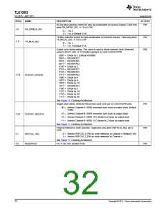
CHANNEL_CONTROL_1 — Address: 0x01 Default: 0x0300
BIT(s)
NAME
DESCRIPTION
ACCESS
RW
Setting this bit high powers down entire data path with the exception that MDIO
interface stays active.
1.15
POWERDOWN
0 = Normal operation (Default 1’b0)
1 = Power Down mode is enabled.
RX mode selection
RW
1.13
RX_MODE_SEL
TX_MODE_SEL
0 = RX mode dependent upon RX_DEMUX_SEL (1.9) (Default 1’b0)
1 = Enables 1 to 1 mode on receive channel
TX mode selection
RW
RW
1. 12
0 = TX mode dependent upon TX_DEMUX_SEL (1.8) (Default 1’b0)
1 = Enables 1 to 1 mode on transmit channel
Channel synchronization hysteresis control on the HS receive channel.
00 = The channel synchronization, when in the synchronization state,
performs the Ethernet standard specified hysteresis to return to the
unsynchronized state (Default 2’b00)
01 = A single 8b/10b invalid decode error or disparity error causes the
channel synchronization state machine to immediately transition from
sync to unsync
HS_CH_SYNC_
HYSTERESIS[1:0]
1.11:10
10 = Two adjacent 8b/10b invalid decode errors or disparity errors cause the
channel synchronization state machine to immediately transition from
sync to unsync
11 = Three adjacent 8b/10b invalid decode errors or disparity errors cause the
channel synchronization state machine to immediately transition from
sync to unsync
Copyright © 2011, Texas Instruments Incorporated
31

 TI [ TEXAS INSTRUMENTS ]