TLK10002
www.ti.com
SLLSE75 –MAY 2011
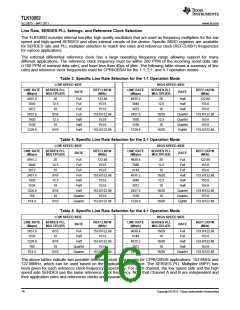
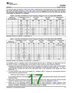
For other line rates not shown in Table 4 and Table 5, valid reference clock frequencies can be selected with the
help of the information provided in Table 6 and Table 7 for the low speed side and high speed side SERDES.
The reference clock frequency has to be the same for the two SERDES and must be within the specified
valid ranges for different PLL multipliers.
Table 6. Line Rate and Reference Clock Frequency Ranges for the Low Speed Side SERDES
SERDES PLL
MULTIPLIER (MPY)
REFERENCE CLOCK
(MHz)
FULL RATE
(Gbps)
HALF RATE
(Gbps)
QUARTER RATE
(Gbps)
MIN
250
MAX
425
MIN
MAX
MIN
MAX
1.7
MIN
0.5
MAX
0.85
1.0625
1.25
1.25
1.25
1.25
1.25
1.25
1.25
4
5
2
2
3.4
4.25
5
1
1
200
425
2.125
2.5
0.5
6
166.667
125
416.667
312.5
250
2
1
0.5
8
2
5
1
2.5
0.5
10
12
12.5
15
20
122.88
122.88
122.88
122.88
122.88
2.4576
2.94912
3.072
3.6864
4.9152
5
1.2288
1.47456
1.536
1.8432
2.4576
2.5
0.6144
0.73728
0.768
0.9216
1.2288
208.333
200
5
2.5
5
2.5
166.667
125
5
2.5
5
2.5
RateScale: Full Rate = 0.5, Half Rate = 1, Quarter Rate = 2
Table 7. Line Rate and Reference Clock Frequency Ranges for the High Speed Side SERDES
REFERENCE CLOCK
(MHz)
FULL RATE
(Gbps)
HALF RATE
(Gbps)
QUARTER RATE
(Gbps)
EIGHTH RATE
(Gbps)
SERDES PLL
MULTIPLIER (MPY)
Min
375
Max
425
Min
Max
Min
Max
3.4
4.25
5
Min
1.5
Max
1.7
Min
Max
4
5
6
6.8
8.5
10
10
10
10
10
10
10
10
3
300
425
6
6
3
3
1.5
2.125
2.5
1
1.0625
1.25
1.25
1.25
1.25
1.25
1.25
1.25
1.25
6
250
416.667
312.5
250
1.5
1
8
187.5
150
6
3
5
1.5
2.5
1
10
12
12.5
15
16
20
6
3
5
1.5
2.5
1
125
208.333
200
6
3
5
1.5
2.5
1
153.6
122.88
122.88
122.88
7.68
7.3728
7.864
9.8304
3.84
3.6864
3.932
4.9152
5
1.92
1.8432
1.966
2.4576
2.5
1
166.667
156.25
125
5
2.5
1
1
5
2.5
5
2.5
1.2288
RateScale: Full Rate = 0.25, Half Rate = 0.5, Quarter Rate = 1, Eighth Rate = 2
For example, in the 2:1 operation mode, if the low speed side line rate is 1.485Gbps, the high-speed side line
rate will be 2.97Gbps. The following steps can be taken to make a reference clock frequency selection:
1. Determine the appropriate SERDES rate modes that support the required line rates. Table 6 shows that the
1.485Gbps line rate on the low speed side is only supported in the half rate mode (RateScale = 1). Table 7
shows that the 2.97Gbps line rate on the high speed side is only supported in the quarter rate mode
(RateScale = 1).
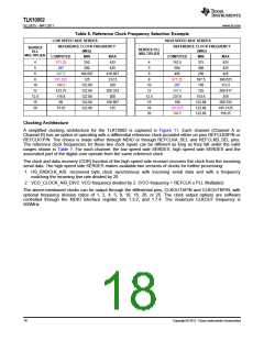
2. For each SERDES side, and for all available PLL multipliers (MPY), compute the corresponding reference
clock frequencies using the formula:
Reference Clock Frequency = (LineRate x RateScale)/MPY
The computed reference clock frequencies are shown in Table 8 along with the valid minimum and maximum
frequency values.
3. Mark all the common frequencies that appear on both SERDES sides. Note and discard all those that fall
outside the allowed range. In this example, the common frequencies are highlighted in Table 8.
4. Select any of the remaining marked common reference clock frequencies. Higher reference clock
frequencies are generally preferred. In this example, any of the following reference clock frequencies can be
selected: 148.5MHz, 185.625MHz, 247.5MHz, 297MHz, and 371.25MHz.
Copyright © 2011, Texas Instruments Incorporated
17

 TI [ TEXAS INSTRUMENTS ]