TLC5928
SBVS120A–JULY 2008–REVISED SEPTEMBER 2008 ................................................................................................................................................. www.ti.com
REGISTER CONFIGURATION
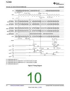
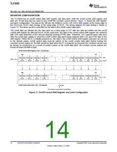
The TLC5928 has an on/off control data shift register and data latch. Both the on/off control shift register and
latch are 16 bits long and are used to turn on/off the constant current drivers. Figure 17 shows the shift register
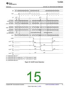
and latch configuration. The data at the SIN pin are shifted in to the LSB of the shift register at the rising edge of
the SCLK pin; SOUT data change at the rising edge of SCLK. The timing diagram for data writing is shown in
Figure 18. The driver on/off is controlled by the data in the on/off control data latch.
The on/off data are latched into the data latch by a rising edge of LAT after the data are written into the on/off
control shift register by SIN and SCLK. At the same time, the data in the on/off control shift register are replaced
with LED open detection (LOD) and pre-thermal warning (PTW) data. Therefore, LAT must be input only once
after the on/off data update to avoid the on/off control data latch being replaced with LOD and PTW data in the
shift register. When the IC is initially powered on, the data in the on/off control shift register and latch are not set
to the default values; on/off control data must be written to the on/off control data latch before turning the
constant current output on. BLANK should be high when the IC is powered on because the constant current may
be turned on at that time as a result of random values in the on/off data latch. All constant current outputs are
forced off when BLANK is high.
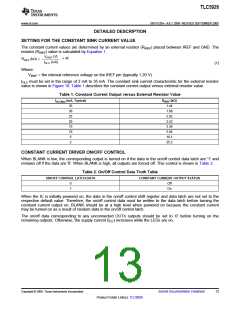
On/Off Control Shift Register (1 Bit ´ 16 Channels)
MSB
15
LSB
0
14
13
12
11
4
3
2
1
SIN
On/Off Data On/Off Data On/Off Data On/Off Data
On/Off Data On/Off Data
On/Off Data On/Off Data
¼
¼
for
for
for
for
for
for
for
for
SOUT
OUT15
OUT14
OUT13
OUT12
OUT3
OUT2
OUT1
OUT0
SCLK
MSB
15
LSB
0
14
13
12
11
4
3
2
1
On/Off Data On/Off Data On/Off Data On/Off Data
On/Off Data On/Off Data
On/Off Data On/Off Data
¼
for
for
for
for
for
for
for
for
LAT
OUT15
OUT14
OUT13
OUT12
OUT3
OUT2
OUT1
OUT0
On/Off Control Data Latch (1 Bit ´ 16 Channels)
16 Bits
To Constant Current Driver Control Block
Figure 17. On/Off Control Shift Register and Latch Configuration
14
Submit Documentation Feedback
Copyright © 2008, Texas Instruments Incorporated
Product Folder Link(s): TLC5928

 TI [ TEXAS INSTRUMENTS ]