THS4531
www.ti.com
SLOS358B –SEPTEMBER 2011–REVISED MARCH 2012
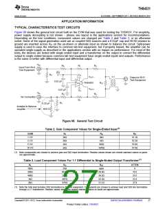
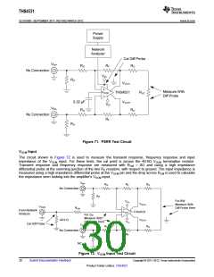
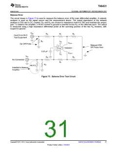
Balance Error
The circuit shown in Figure 73 is used to measure the balance error of the main differential amplifier. A network
analyzer is used as the signal source and the measurement device. The output impedance of the network
analyzer is 50Ω and is DC coupled. RIT and RG are chosen to impedance match to 50Ω and maintain the proper
gain. To balance the amplifier, a 49.9Ω resistor to ground is inserted across RIT on the alternate input. The output
is measured using a high impedance differential probe at the summing junction of the two RO resistors, with
respect to ground.
VIN+
RG
RF
RO
Input From 50-Ω
Test Equipment
RIT
VS+
VOUT–
THS4531
VOUT+
Cal Diff Probe
Measure With
Diff Probe Here
+
VOCM
–
0.22 μF
VS–
VIN-
RG
RO
No Connection
RF
RIT
49.9 Ω
Installed to Balance
Amplifier
Figure 73. Balance Error Test Circuit
Copyright © 2011–2012, Texas Instruments Incorporated
Submit Documentation Feedback
31
Product Folder Link(s): THS4531

 TI [ TEXAS INSTRUMENTS ]